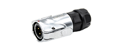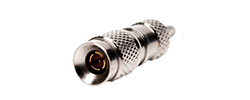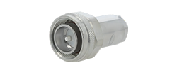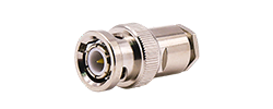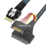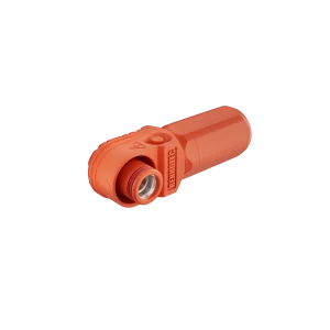
60A - 120A
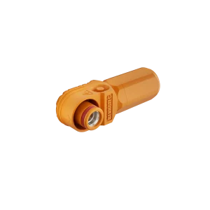
125A - 200A
250A - 350A
400A - 480A
CABLE ASSEMBLY & INSTALLATION
Choose the cable arrangement that fits your route, your installation work and the way you will maintain the machine.
A molded M12 cordset makes sense when you can specify the cable and connector ends before installation. A field-wireable connector lets you terminate a suitable cable during assembly or on site. Between them is an often useful option: a molded connector at the device, with a free cable end for wiring inside a cabinet.
THE CONNECTION YOU NEED
A cordset is a cable supplied with connectors already attached. A molded cordset has a molded body around the cable termination. A field-wireable connector, also called field-attachable or field-assembly, is supplied for termination to a suitable cable. It can be assembled at a workbench as well as at the installation site.
Select both mating interfaces, the end-to-end wiring and the finished cable length.
Prepare and wire the free end; leave enough cable for the installed route and termination.
Match cable diameter and conductor size, then prepare and assemble according to the connector instructions.
Single-ended and double-ended are established cordset arrangements; see Banner’s cordset range. Renhotec’s M12 catalog, printed pages 119–120, shows single-ended molded configurations.
AT THE CABLE END
A threaded M12 coupling joins the connector to its mating port. Inside a field-wireable connector, the wires may use screw terminals, solder cups, crimp contacts or another specified termination. “Screw-locking” and “screw-terminal” describe different connections.
A-coded · 5-pin male · angled · PVC cable
A-coded · 4-pin male · angled · screw contacts
Both examples have angled cable exits. The five-pin molded cable and four-pin field-wireable plug serve different contact configurations; they are not interchangeable substitutes. Photos are not shown to the same scale.
Swipe across the table to compare columns.
| Decision | Molded cordset | Field-wireable connector |
|---|---|---|
| Cable selection | Specify cable type, finished length, both ends and wiring. | Match the cable’s jacket diameter, conductors and construction to the connector. |
| Local termination | None at the molded end. A single-ended cordset still requires work at its free end. | Prepare the cable; terminate contacts; assemble the entry, housing and any shield connection. |
| Length adjustment | Double-ended: order the finished length. Single-ended: prepare the free end as permitted. | Cut after measuring the route. Include preparation and service allowances. |
| Damaged connector | Plan for replacement of the assembly or an approved repair approach. | Replacement may be possible if the cable remains suitable and the connector’s instructions permit it. |
Pre-assembled describes the supply condition; overmolded describes the construction. A supplier can also assemble a cable using field-attachable connectors. Ask which construction you are being quoted when a listing says only “M12 cable assembly.”
No. Renhotec’s catalog includes screw, solder-cup and crimp versions on printed pages 82–84. Other manufacturers also offer spring-based connections; binder’s cage-clamp M12 range is one example. Select the termination and its required tools as part of the connector specification.
BEFORE YOU ORDER THE LENGTH
A cable can fit through a passage that its connector cannot. Check the largest part that must pass through, including the coupling, body and any angled cable exit. An M12 interface name is not the outside diameter of the complete connector.
Check the complete connector envelope, including the coupling and any angled outlet.
Use a single-ended cordset for terminals, or assemble a suitable field-wireable connector after routing.
If the far end connects to cabinet terminals, a single-ended molded cordset may solve a restricted-access problem. If that end also needs an M12 connector, check whether it can be assembled after routing. Otherwise, change the route or provide access for the complete connector.
Follow the intended tray, clamps and bends rather than the straight-line distance between ports. Include the service allowance that the machine needs. Confirm where the supplier measures the finished cable length.
Check access for fingers or the specified tool, the position of adjacent ports, the required bend radius and the direction of an angled outlet. A connector can fit the port yet leave too little room for its cable.
For repeated builds, settle the route and length convention on the first installation before ordering the production quantity. That gives purchasing a repeatable assembly specification rather than a cable length estimated from a layout sketch.
CABLE, CONNECTOR & ENVIRONMENT
For a field-wireable connector, check cable outside diameter and conductor size separately. The cable entry works on the outside of the cable; the electrical terminals work on individual conductors. A cable that fits one may fail the other.
Outer jacket → insulated cores → exposed conductors
One core, enlarged
Choose a layer to see which part of the cable it describes.
Measured over the outer jacket. Match it to the cable-entry sealing and clamping range.
Surrounds the metal conductor. It is not included in the conductor’s metal cross-sectional area.
Match the conductor size and type to the electrical terminal.
For example, Phoenix Contact’s 1513253 connector data sheet lists a 4–8 mm cable outside diameter and a separate 0.14–0.5 mm² conductor range. Those values belong to that connector; they are not a general M12 range.
Swipe across the table to compare columns.
| Check | What must agree | What is insufficient on its own |
|---|---|---|
| Mating interface | Coding, contact count, contact gender and the required mating arrangement. | “M12” on both product names. |
| Electrical path | Each contact’s function and end-to-end mapping, plus the applicable ratings. | Matching wire colors or matching connector shells. |
| Cable entry | Specified jacket diameter and construction, with the required seal and assembly method. | A conductor-size entry or a cable-entry thread designation. |
| Wire termination | Permitted conductor size and type, preparation, ferrules where applicable, and the specified tools. | Assuming every terminal accepts the same stranded wire or ferrule. |
| Operating conditions | The selected assembly’s temperature, mechanical movement, chemicals and ingress-protection conditions. | “Industrial,” a jacket-material name, or an IP number without its conditions. |
Field-wireable does not mean unsealed. Banner’s 4-pin A-code field-wireable data sheet specifies IP67 with a properly sized cable and a fully mated connector. Renhotec’s field-assembly catalog page 79 and molded-cable pages 119–120 also state IP67 in the mated condition.
A molded termination removes the need to assemble that cable entry locally. The mating interface still needs the correct counterpart and proper assembly. An exposed free cable end is not protected simply because the molded connector has an IP rating.
Choose the required cable construction, connector and shield termination together. A metal housing alone cannot establish the shield connection, and electrical continuity alone cannot establish Ethernet performance. Use the assembly instructions and verification requirements for the selected system. Do not choose a data cable by borrowing the wiring of an A-coded sensor cable.
For the contact-mapping step in a sensor installation, the M12 A-coded 4-pin and 5-pin reference explains viewing direction and pin identification. The device’s signal diagram remains the basis for the actual connection.
INSTALLATION & SERVICE
A molded cordset reduces termination work at its finished ends. A field-wireable connector puts cable preparation, contact termination and housing assembly into your installation process. Either can be appropriate; the choice depends on whether that work fits the people, tools and access available.
When the route and interfaces are stable, compare a stocked or specified cordset against assembling the same configuration yourself. Include handling, preparation and inspection in the comparison. Field-attachable connectors can also be assembled in production; quantity alone does not rule them out.
A field-wireable end can accommodate a length set after routing. Where the far end goes to terminals, a single-ended cordset offers much of that flexibility while retaining the molded device end. Both need a suitable cable and sufficient service length.
A replaceable connector is useful only if the remaining cable is sound, has enough length and fits the new connector. Damage along the cable or loss of the required shield or environmental performance can make complete replacement the better route. Follow the equipment’s repair requirements before changing the original construction.
The connector price is only one line of the comparison. For field assembly, include the cable, connector, required tooling, assembly time and checks. For a cordset, include the specified assembly and any free-end termination. For both, consider rework, spare availability and how replacement affects machine access.
Use the same required length, interfaces, cable properties and verification scope for both quotations. A lower price for a different jacket, unshielded construction or fewer completed terminations is not a like-for-like saving. Stock cordsets and custom assemblies also have different lead-time and ordering conditions; obtain those for the actual configuration.
FROM CHOICE TO CONFIGURATION
Once you have chosen the assembly form, specify the cable exit as well as the mating face. An angled end can help direct the cable away from nearby equipment, but its orientation must suit the actual port position and service access.
The five-pin molded cable shown above provides a PVC-jacketed, single-ended configuration. Match its contacts and wiring to the device, then specify the routed length and required cable properties.
The four-pin field-assembly plug shown above uses screw contacts. Its PG7 designation is not a cable-diameter range; obtain the permitted cable and conductor ranges for the selected configuration.
For other genders, contact counts, angles or termination types, use the M12 product range. Specify both ends when requesting a complete cordset.
Provide the device and mating-port references, coding and contact arrangement, end-to-end wiring, routed length and measurement convention, cable requirements, and operating conditions. For a field-wireable connector, add the cable data sheet and the assembly tools or termination method you intend to use.
If two constructions remain suitable, request quotations against that same specification. The resulting comparison will show the difference in supplied work as well as the product price.
Discuss an M12 cable configuration