60A - 120A
125A - 200A
250A - 350A
400A - 480A
SFF-8654 · server & storage interconnects
A SlimSAS port can lead to SATA drives, a SAS backplane or PCIe storage. Choose the cable around the signal path, then match the ends, power and physical route.
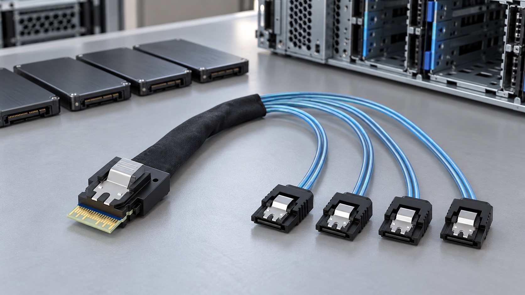
A SlimSAS cable is an internal cable assembly using the SFF-8654 connector family. Depending on the equipment and the cable wiring, it can carry SAS, SATA or PCIe signals. The name identifies a connector family; it does not tell you which devices a particular port can operate.
Start with the device you want to connect and the documented function of the host port. A SATA breakout needs SATA-capable host connections. An NVMe drive needs a PCIe path. A cable with the correct plugs cannot supply a protocol that the controller does not provide.
For example, Supermicro documents the X14SAE/X14SAE-F SlimSAS 8i port as a PCIe connection serving two x4 U.2 links. A different manual, for the X14SBW-TF/F platform, describes SlimSAS connectivity for eight SATA devices or two PCIe x4 devices. Those are model-specific arrangements, not capabilities of every SlimSAS receptacle. See the X14SAE port description and X14SBW connection description.
SlimSAS, Slim SAS and Slimline SAS appear in supplier catalogs and equipment manuals. Add SFF-8654 and the connector size when specifying a cable. That avoids relying on a shortened sales name that leaves the mating interface unclear.
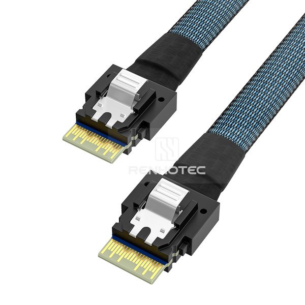
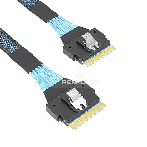
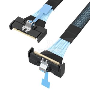
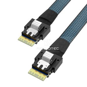
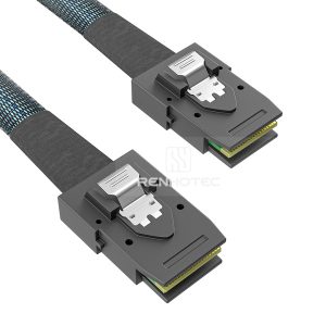
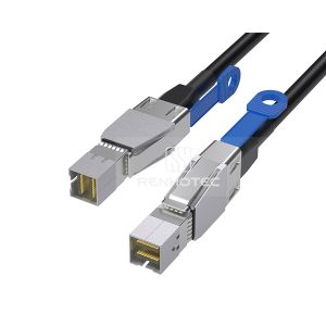
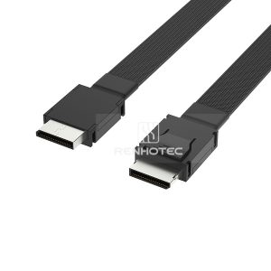
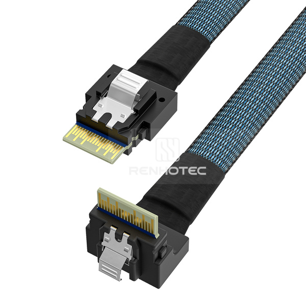
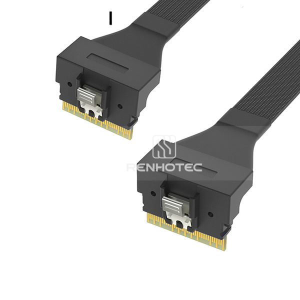
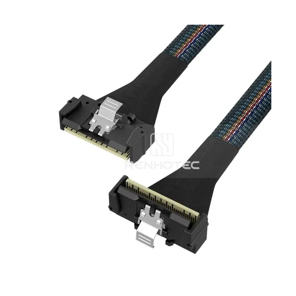
The common 4i and 8i forms have 38 and 74 contacts respectively; IOI identifies both forms in its SFF-8654 assembly specification. Contacts include more than the high-speed signal paths, so contact count is not a drive count. The photographs above are separate product views, not a dimensional scale comparison.
Do not order a 4i plug for an 8i receptacle on the assumption that it will occupy half the opening. Select the correct mating form. Where one 8i port must connect to two 4i ports, use an assembly designed for that arrangement and establish what signals each branch carries.
| Label | What it identifies | Still needed |
|---|---|---|
| SFF-8654, 4i or 8i | Connector family and form | Mating drawing, orientation and cable wiring |
| SAS, SATA or PCIe | The signal system used by the equipment | Controller support and the destination’s requirements |
| PCIe generation or SAS rate | A performance target for the implementation | Qualification for the particular assembly, length and system |
SlimSAS is also distinct from Mini-SAS HD and MCIO. SFF-8643, SFF-8087 and SFF-8654 should not be treated as interchangeable part numbers. If the starting point is an unidentified connector, use the server and storage cable family guide before selecting a branch arrangement.
An 85Ω or 100Ω impedance value does not identify a lane map or protocol. Put the required impedance, target generation and signal assignment on the cable specification using the equipment requirements. Amphenol lists PCIe 4.0/5.0 support for particular SlimSAS implementations; that rating cannot be transferred to every supplier’s assembly or length.
A SlimSAS-to-SATA breakout groups several individual SATA signal connections at one host-side connector. In the Renhotec range, RHT-726-1001 has one 4i end and four SATA branches; RHT-726-1019 has one 8i end and eight SATA branches. Choose the arrangement that corresponds to the host port’s documented SATA connections.
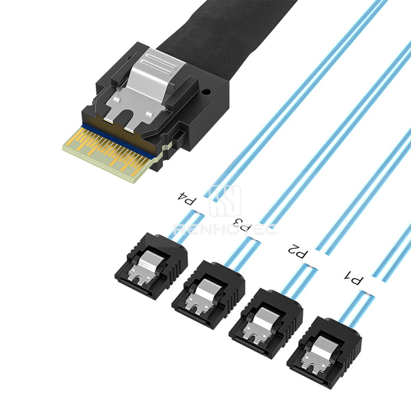
Four separate destinations
The branch labels help preserve the drive-to-port map during assembly and servicing. These SATA ends carry signals; the drives need their own power connections.
Confirm the direction of the intended connection. A host-to-drive fanout and an assembly that gathers individual motherboard SATA ports into a backplane connector perform different wiring jobs. Descriptions with the same connector names are not enough to establish that they can be reversed. Request the host and device assignments on the cable drawing.
For a four-drive installation, label each branch against the chassis bay before closing the system. Record the relationship between the controller port, branch label and drive position. If a drive later disappears, this lets a technician inspect the intended path without unplugging unrelated drives or guessing from cable position.
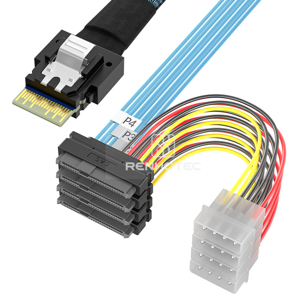
The SAS breakout arrangements use SFF-8482 drive ends. Renhotec lists four branches on RHT-726-1008 and eight on RHT-726-1022, with separate 4-pin peripheral power connections. The chosen controller must support the drives; attaching a SAS-shaped connector to a SATA-only host does not provide a SAS controller.
Tri-mode is a controller capability, not a universal property of an 8i cable. Broadcom’s 9500-8i HBA, for instance, is a particular tri-mode adapter with one x8 SFF-8654 connector. Its supported device arrangements do not establish compatibility for another controller or for every assembly with that connector.
For an NVMe U.2 drive, the signal path must carry PCIe to the drive-side SFF-8639 connection. A 4i-to-U.2 assembly provides a physical route for one drive connection. An 8i-to-two-U.2 assembly provides two physical branches, but both drives work only when the host and wiring provide the required independent PCIe links.
Conceptual host allocations, not a pinout. An 8i connector alone does not establish either arrangement or permit both at once.
If the motherboard manual specifies two x4 links, match the branches to those assignments. If it exposes a single x8 PCIe link, a passive Y cable does not turn that link into two independently operating endpoints. The required split must be supported and configured by the platform, or supplied by appropriate active hardware. Do not assume that a BIOS option exists because a cable has two ends.
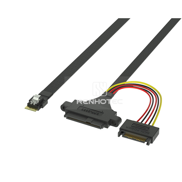
Signal and power
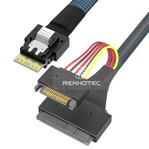
RHT-726-1020 pairs a SlimSAS 4i signal end with a U.2 drive end, mounting ears and a separate 15-pin power connector.
Allow space for the drive connector, its mounting points and the power lead. The signal route alone is not a complete drive installation.
First match the host connector and required number of drive ends, then compare the available power connection and mounting features. All five configurations below use U.2 SFF-8639 drive ends.
| Renhotec SKU | Host form | U.2 ends | Power connection | Mounting ears |
|---|---|---|---|---|
| RHT-726-1020 | 4i | 1 | 15-pin power connector | Listed |
| RHT-726-1015 | 8i | 1 | 4-pin peripheral power connector | Listed |
| RHT-726-1013 | 8i | 2 | 4-pin peripheral power connectors | Not stated |
| RHT-726-1014 | 8i | 2 | 4-pin peripheral power connectors | Listed |
| RHT-726-1018 | 8i | 2 | 15-pin power connectors | Listed |
“Not stated” means the configuration listing does not specify mounting ears; it does not mean they are absent. Drive-end count describes the assembly, not the host’s usable link count. Confirm the wiring and mounting drawing for the selected SKU.
Do not infer U.3 support from a similar drive-side housing. Broadcom’s controller cable guide lists separate U.2 and U.3 arrangements, alongside controller-specific compatibility. Renhotec’s configurations described here are identified as U.2; a U.3 project requires confirmation of the exact host, drive, backplane and cable assignment.
For a host documented to provide two independent x4 PCIe links through SlimSAS 8i, two U.2 endpoints narrow the list to 1013, 1014 and 1018. A specified 4-pin power connection with mounting ears points to RHT-726-1014; a specified 15-pin power connection with ears points to RHT-726-1018. The single-U.2 1015 is a different physical arrangement despite also using an 8i host end. Check the chosen drawing’s branch map and mounting dimensions against the two drive positions.
A cable to a backplane is part of a longer route. Find the receiving backplane port, the drive bays it serves, and the protocols supported on those bays. A connector on the backplane may represent several independent links, a particular group of drive positions, or a path through other hardware. Its shape does not describe that downstream arrangement.
A useful example from a controller cable guide
Broadcom lists 05-60002-00 for a specified NVMe backplane connection and 05-60003-00 for SAS connections. Both use an x8 SFF-8654 host end and two x4 SFF-8643 ends. The shared connector names do not make the assemblies interchangeable.
See the 95xx adapter cable table, page 3That distinction matters when ordering a SlimSAS-to-Mini-SAS HD assembly. Renhotec’s RHT-726-1003 has an 8i end and two SFF-8643 ends; RHT-726-1006 connects 4i to SFF-8643. These descriptions establish endpoint arrangements. Select the wiring for the intended host and backplane, rather than assigning a protocol to the product from its photographs.
Ask for the sideband requirements as well as the high-speed pairs. Depending on the platform, supporting signals may be needed for management, device detection or other functions. The specification should identify which signals are connected and how they are assigned. A continuity check for the obvious data paths alone cannot establish every system function.
A replacement request is easier to resolve when it includes the original cable part number, controller model, backplane model and revision, and photographs of the port labels. If the old part is unavailable, use those details to compare a candidate assembly against the required drawing. Matching only the two connector names leaves the central compatibility question unanswered.
A right-angle exit can help in a shallow enclosure, but it can also point the cable directly into a heatsink or a neighboring connector. Define the exit using a drawing or an annotated photograph of the installed receptacle. Words such as left, right, up and down change meaning when the board is rotated.
Measure along the planned installed path, including the approach to each connector. A straight-line measurement between sockets misses the space needed to turn, pass a chassis divider or reach a drive after the branch point. For a breakout, record both the shared trunk and the individual branch lengths. Unequal bay distances may make equal branches awkward to service.
Leave room to operate the latch without pulling on the cable. Check the route with the lid, fan assembly and drive carrier in their installed positions. Follow the assembly supplier’s bend and handling limits; there is no useful universal bend-radius number that can be assigned from “SlimSAS” alone.
LP SlimSAS deserves its own mechanical check. Amphenol presents standard and low-profile SlimSAS implementations separately. Treat an LP label as a reason to obtain the mating drawing, not as assurance that any low-profile cable will fit an existing receptacle.
Use the destination and physical route to narrow the options. The links open the live SlimSAS configuration list, where each SKU can be matched to its product image. Confirm the electrical assignment, qualified length and required performance for the selected assembly before ordering.
Compare the five U.2 configurations above by host connector, drive-end count, power connection and mounting ears.
Some projects start at an MCIO port and terminate at SlimSAS. Those assemblies sit in the MCIO configuration range. The MCIO guide’s direct and breakout discussion explains the host-link distinction when that is the starting interface.
Begin with the intended configuration, not a random sequence of cable swaps. Record which drives are visible, the controller or BIOS view used, and the port-to-bay map. That gives each inspection a specific question to answer.
| Observation | Check first | Useful evidence |
|---|---|---|
| No SATA drives appear | Whether this SlimSAS port actually exposes SATA, breakout direction, seating and drive power | Host manual, cable wiring drawing and power path |
| Only one of two NVMe drives appears | Independent host-link allocation, branch mapping and power to both drives | Port topology, relevant firmware settings and branch labels |
| A backplane change breaks detection | Backplane model/revision, port assignment and required sidebands | Old and new port maps with the cable part number |
| The connection works only with the lid removed | Mechanical pressure, connector seating and interference along the installed route | Route photographs with the enclosure assembled |
| The link runs below its intended generation | Equipment capabilities, negotiated link status and qualification of the complete route | Controller diagnostics, assembly specification and system test conditions |
Where equipment procedures permit substitution, change one element at a time and record the result. A known-good assembly can help isolate a path problem; it does not establish the original failure mechanism by itself. Power down and service the equipment according to its instructions unless the complete system is designed for the intended hot-swap procedure.
Give Renhotec the host and destination models, port labels, required protocol and generation, and the number of independent links or drives. Add an installed-route sketch, branch lengths where applicable, exit directions and the available power connector. Include the original part number or an approved wiring drawing for replacement projects.
Example · four SATA drives
“Our motherboard manual assigns four SATA channels to this SlimSAS 4i port. We need four SATA signal branches for the numbered drive bays; drive power is separate. Please check RHT-726-1001 against the attached host pin assignment and route sketch, including branch mapping and the required lengths.”
If a field is not yet known, send the corresponding manual page or a photograph of the port label. This gives the technical review a concrete starting point and avoids choosing a cable from connector appearance alone.