60A - 120A
125A - 200A
250A - 350A
400A - 480A
Server & storage interconnects
Compare six cable families for motherboard, controller, backplane and drive connections. Check the wiring, power and fit before ordering.
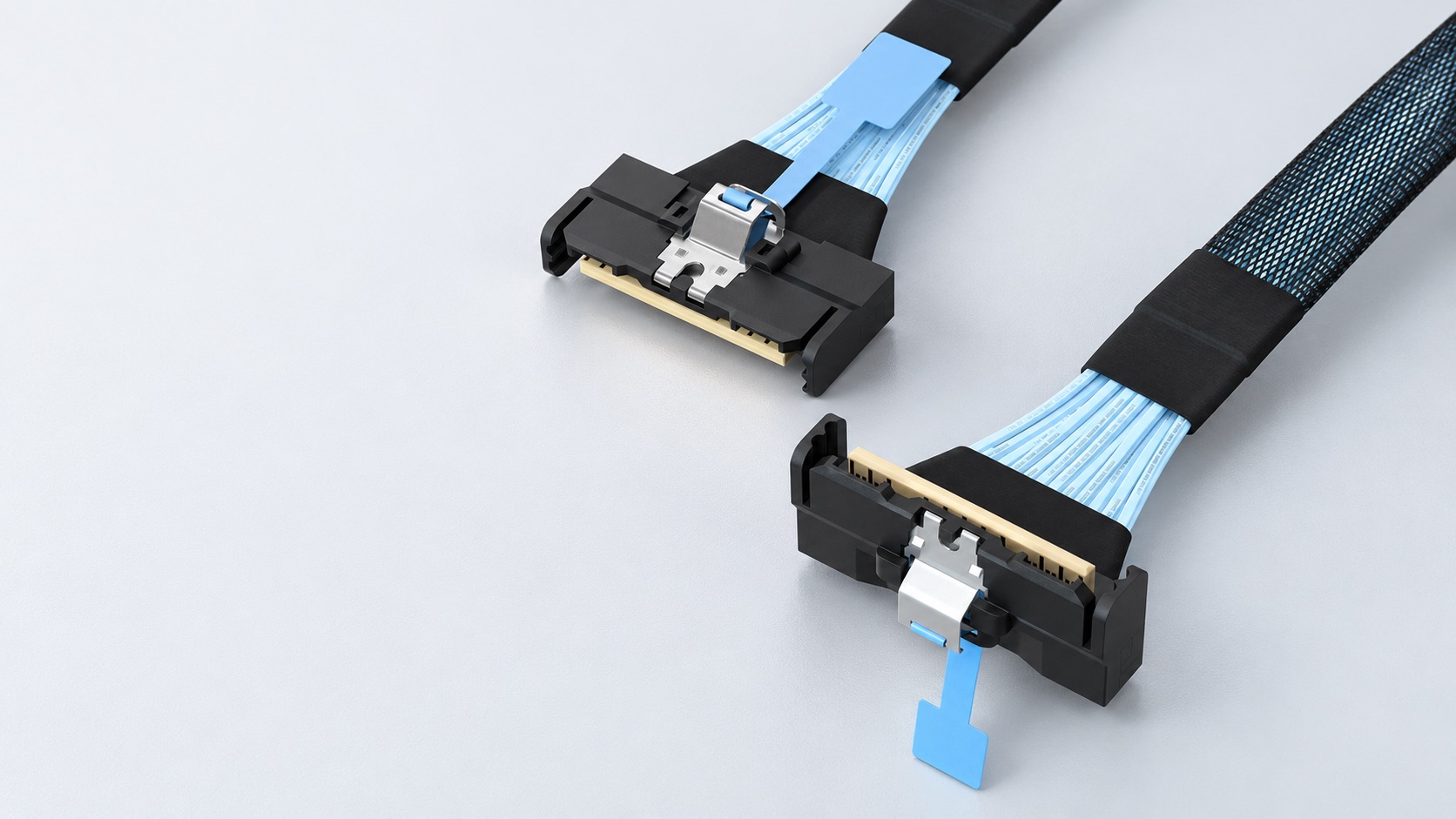
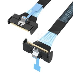
MCIO x8 cable with straight and right-angle ends. Illustration.
01 / Start with the connection
A cable search often begins with a connector name: MCIO, SlimSAS or Mini-SAS HD. Before comparing part numbers, write down the two devices the cable must join. A motherboard-to-backplane connection needs a different review from a controller-to-drive connection, even when the plugs look familiar.
The equipment manual identifies the port’s signals; a photograph shows the housing, latch and cable exit. Together they help distinguish a mechanical match from a usable system connection.
Choose the family from the installed ports first. Use the family overview below to identify the interface, then compare the configurations for your connection. Renhotec’s High-Speed I/O Cable Assemblies range provides the corresponding product configurations.
02 / Recognize the interfaces
The names below appear at different levels of a cable description. MCIO and SlimSAS identify connector families; U.2 commonly describes the drive-side interface. A cable can therefore belong in more than one search: an MCIO-to-U.2 assembly has an MCIO end and a U.2 end. Read the complete endpoint description before comparing two listings.
| Family | Names to recognize | First selection question |
|---|---|---|
| MCIO | x4 / x8 configurations | Which port, lane arrangement and exit direction? |
| SlimSAS | SFF-8654, 4i / 8i | What protocol and wiring does this port require? |
| Mini-SAS | SFF-8087 / SFF-8088 | Internal or external, and direct or breakout? |
| Mini-SAS HD | SFF-8643 / SFF-8644 | Which connector and electrical implementation? |
| OCuLink | 4i; SFF-8611 / SFF-8612 references | Which cable and mating-port specification? |
| U.2 | SFF-8639 drive-side connection | What host connection and power feed are needed? |
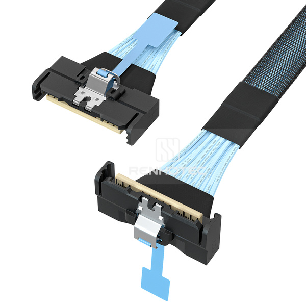
MCIO is a compact connector family used in server and storage interconnects. Molex’s MCIO overview shows multiple circuit counts, plug designs and cable exits for space-constrained equipment.
Renhotec’s listed x4 and x8 assemblies include direct cables, x8-to-two-x4 breakouts and connections to other interfaces. A direct cable carries the connection to one endpoint; a breakout routes it to separate connectors. The platform’s lane arrangement determines whether those branches can serve the intended devices.
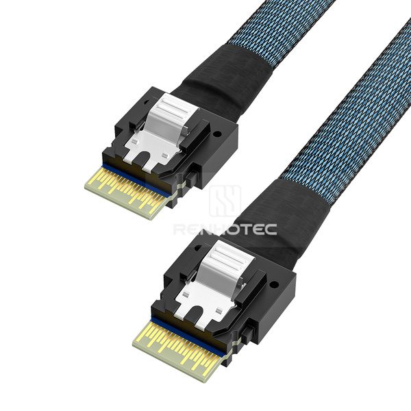
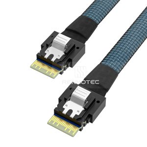
SlimSAS uses the SFF-8654 connector form factor; 4i and 8i are common labels in cable listings. Applications include SAS and PCIe connections, as shown in Amphenol’s internal interconnect overview. The equipment port determines the electrical use.
Renhotec’s range includes SlimSAS-to-SlimSAS cables, SATA breakouts and assemblies with Mini-SAS HD or U.2 at the other end. This makes the full endpoint description useful: “SlimSAS 8i to two Mini-SAS HD” describes a different physical route from “SlimSAS 4i to four SATA.”
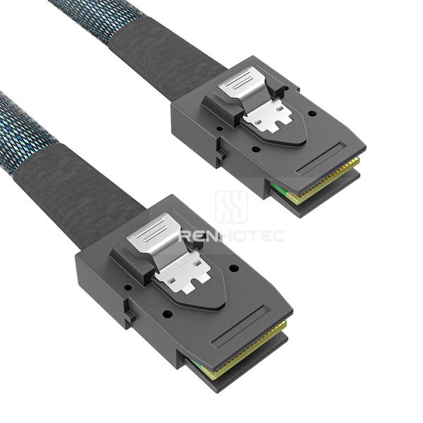
In this range, SFF-8087 identifies internal Mini-SAS configurations and SFF-8088 identifies external ones. Both may appear under “Mini-SAS cable,” so the SFF reference is the quickest way to separate the two when reading a listing.
A forward breakout connects an SFF-8087 controller port to individual SATA drives; a reverse breakout connects individual SATA host ports to a compatible SFF-8087 backplane. Direction describes endpoint roles and wiring, not one-way data flow.
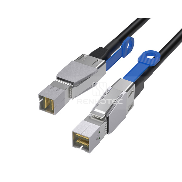
Mini-SAS HD uses SFF-8643 for the internal configurations discussed here and SFF-8644 for external configurations. These interfaces differ from Mini-SAS SFF-8087 and SFF-8088. For example, an internal cable joining an SFF-8643 controller to an SFF-8087 backplane needs a different connector at each end.
Check the electrical role as well as the connector: some SFF-8643 ports carry PCIe for an NVMe drive. Match the equipment’s specified port assignment before selecting an assembly.
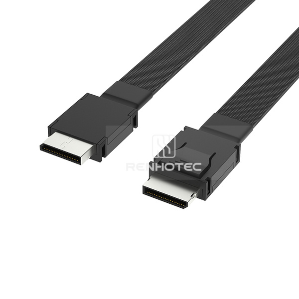
OCuLink appears in PCIe cabling, including storage systems. Documentation may refer to SFF-8611 and SFF-8612 for the cable and mating connector. Renhotec’s listed 4i configurations include same-interface assemblies and connections to other storage interfaces.
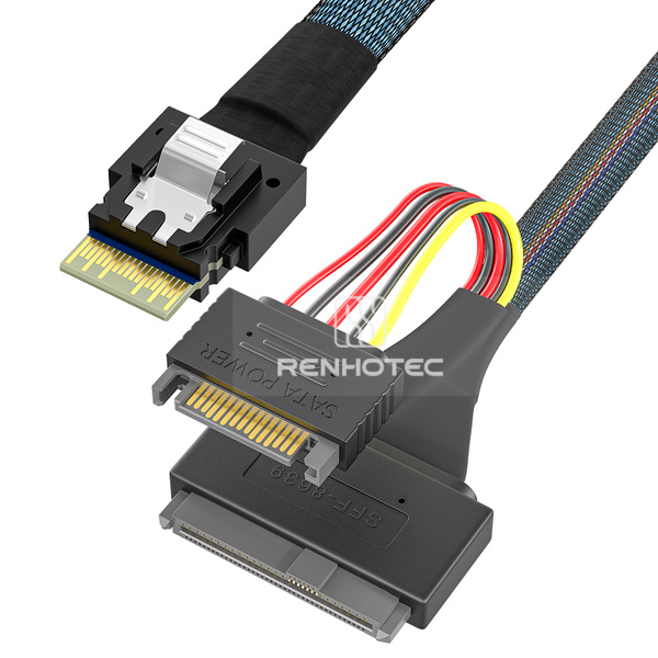
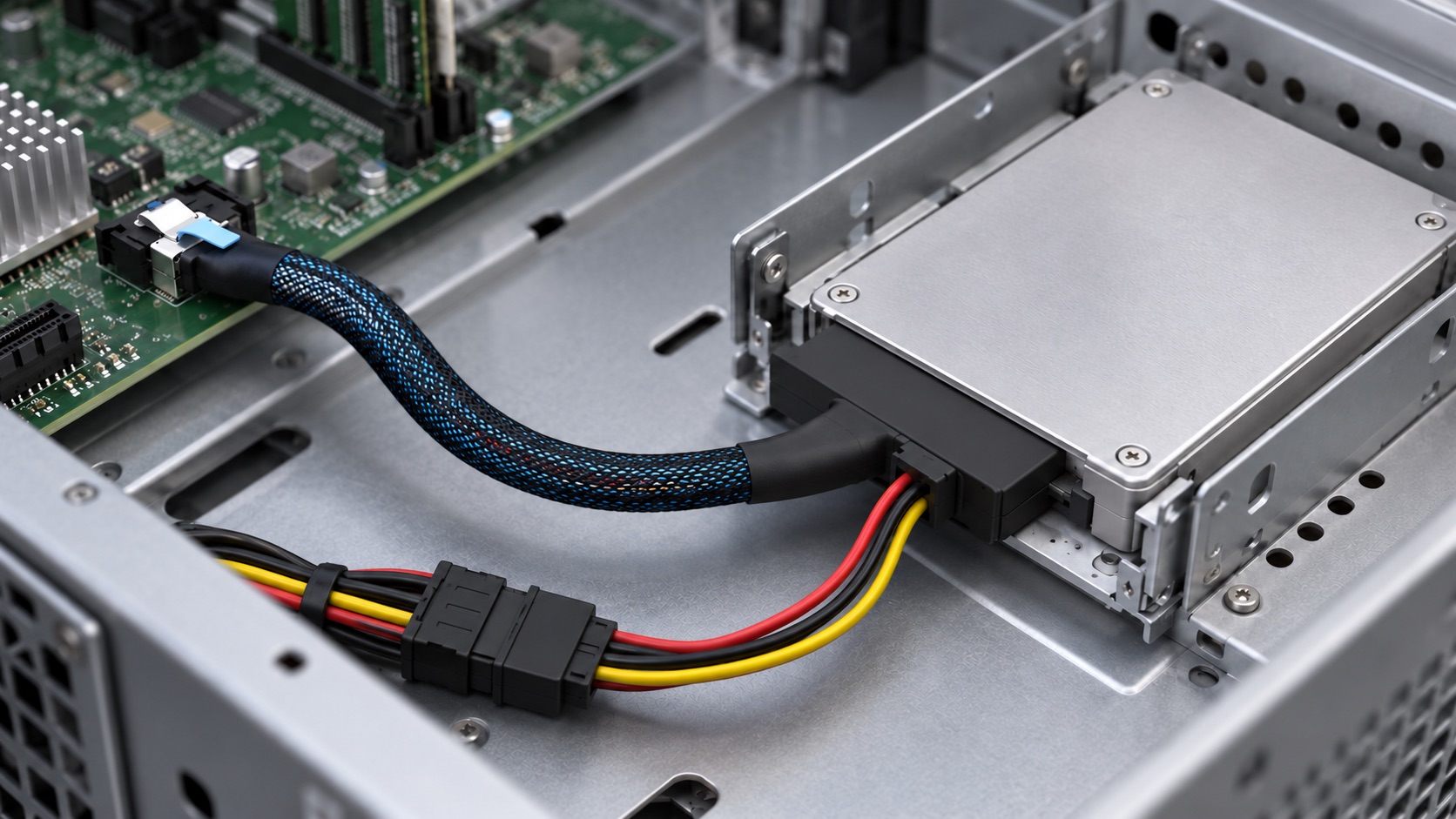
U.2 is commonly associated with the drive-side connection of a 2.5-inch NVMe SSD. SNIA’s SSD form-factor guide relates U.2 to the PCI Express SFF-8639 module specification. The host end may use MCIO, SlimSAS or another interface, so “U.2 cable” is only part of the description.
For a direct-drive assembly, include the separate power feed as well as the host signal route. A U.2 cable listing does not establish U.3 system compatibility: the drive, host and backplane must support the proposed arrangement.
03 / Compare the interfaces
MCIO and SlimSAS are different connector families with overlapping server and storage uses. Their plugs are not interchangeable. In an existing system, choose the assembly that matches both installed ports. A cable can have MCIO at one end and SlimSAS at the other when the equipment supports that connection.
| Selection point | MCIO | SlimSAS |
|---|---|---|
| Physical interface | Mini Cool Edge connector family; match the specified MCIO receptacle | SFF-8654 connector family; match the specified SlimSAS receptacle |
| Labels in this range | x4 and x8; straight, angled and breakout arrangements | 4i and 8i; same-interface cables and breakouts |
| Where you encounter it | Compact server and storage links; PCIe interconnect applications | Storage-controller and backplane links; SAS or PCIe applications depending on the port |
| Representative routes | MCIO to MCIO, MCIO to SlimSAS, or MCIO to U.2 | SlimSAS to SlimSAS, SATA, Mini-SAS HD or U.2 |
| Mechanical choice | Plug exit direction, latch access and clearance around the installed port | Connector size, cable exit and the space needed for the selected branch arrangement |
| Performance comparison | Use the rating of the exact assembly at the required length and the equipment’s supported link mode. Neither family name establishes a universal speed ranking. | |
Molex specifies 0.60 mm pitch for its MCIO family, and Amphenol specifies the same pitch for its SlimSAS U10 connectors. Pitch alone therefore cannot identify a mating interface. Product-specific generation or data-rate claims in those manufacturers’ literature also do not rate a Renhotec assembly.
| Comparison | Direct answer | Selection consequence |
|---|---|---|
| Mini-SAS vs Mini-SAS HD | Different physical interfaces: internal SFF-8087 vs SFF-8643; external SFF-8088 vs SFF-8644 | An SFF-8643 controller and an SFF-8087 backplane need a cross-interface cable, not a same-end replacement. |
| SFF-8643 vs SFF-8654 | Internal Mini-SAS HD vs SlimSAS. These references identify connectors, not a single protocol. | An 8i SlimSAS-to-two-Mini-SAS-HD assembly routes one main connector to two ports. Its wiring must match the backplane application. |
| SlimSAS vs OCuLink | Separate connector families that can both appear in PCIe storage paths | Select by the host and destination ports. “PCIe cable” alone leaves the mechanical interfaces unspecified. |
| OCuLink vs U.2 | They can be the two ends of one assembly: OCuLink at the system side and SFF-8639 at the drive | For a direct U.2 drive connection, include the power provision as well as the signal connection. |
What physically mates?
Exact interface & orientationWhat does the port carry?
Equipment specificationHow is the link arranged?
x4 / x8 & branch mappingThe connector defines the mating interface; the port assignment defines the signals. For PCIe, x4 means four lanes and x8 means eight. A passive x8-to-two-x4 cable divides the assigned lanes between branches, so the host must provide two usable x4 links for two independent endpoints. It does not give each branch an x8 link or configure the host.
Identical endpoint names can also hide different wiring. Broadcom lists 05-60002-00 for a specified NVMe backplane arrangement and 05-60003-00 for SAS, both with SFF-8654 and two SFF-8643 ends. See page 3 of its controller cable guide. Those references demonstrate the distinction; they do not establish equivalence to a Renhotec SKU.
04 / Plan the connection
Sketch the intended connection before selecting a cable. Label the host port, destination and each branch. This makes it easier to spot a missing power connection or an incorrect assumption about which device controls the link.
Same family at both ends
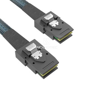
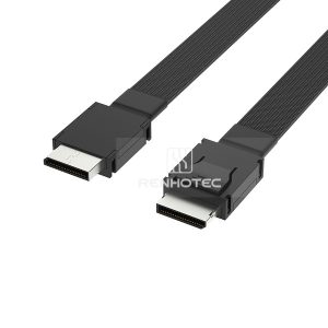
RHT-726-0001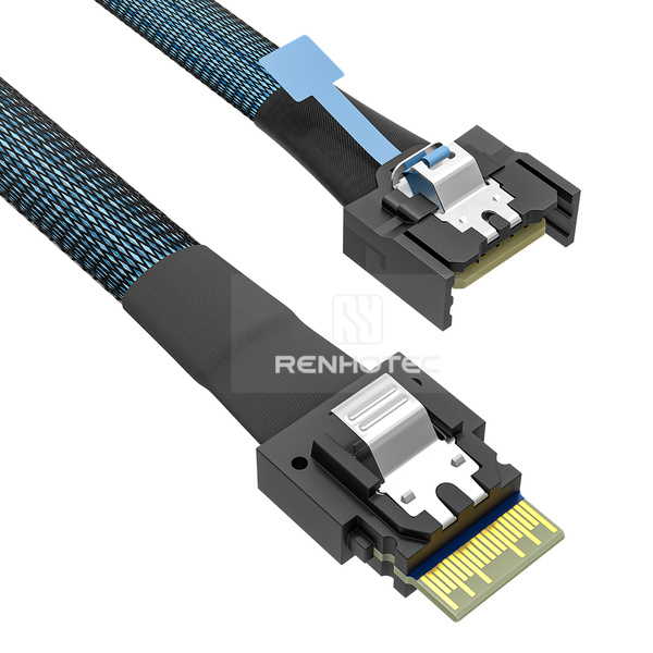
Different connector families
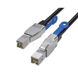
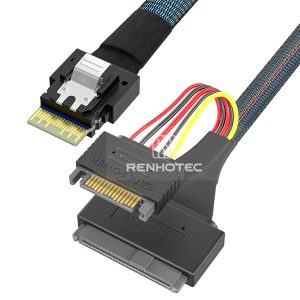
RHT-726-0007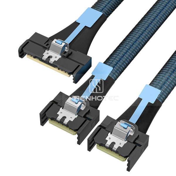
One main end, two branches
RHT-726-0003A direct assembly joins two endpoints without separate branches. The two plugs can have different exits even within the same family: for example, straight at the controller and right angle at a backplane. Describe the orientation at each end independently.
A cross-interface assembly joins different connector families, such as MCIO and SlimSAS. It is useful when the host and destination use unlike receptacles for a supported electrical connection. Record both endpoints in the cable name so a supplier can distinguish it from a same-interface assembly.
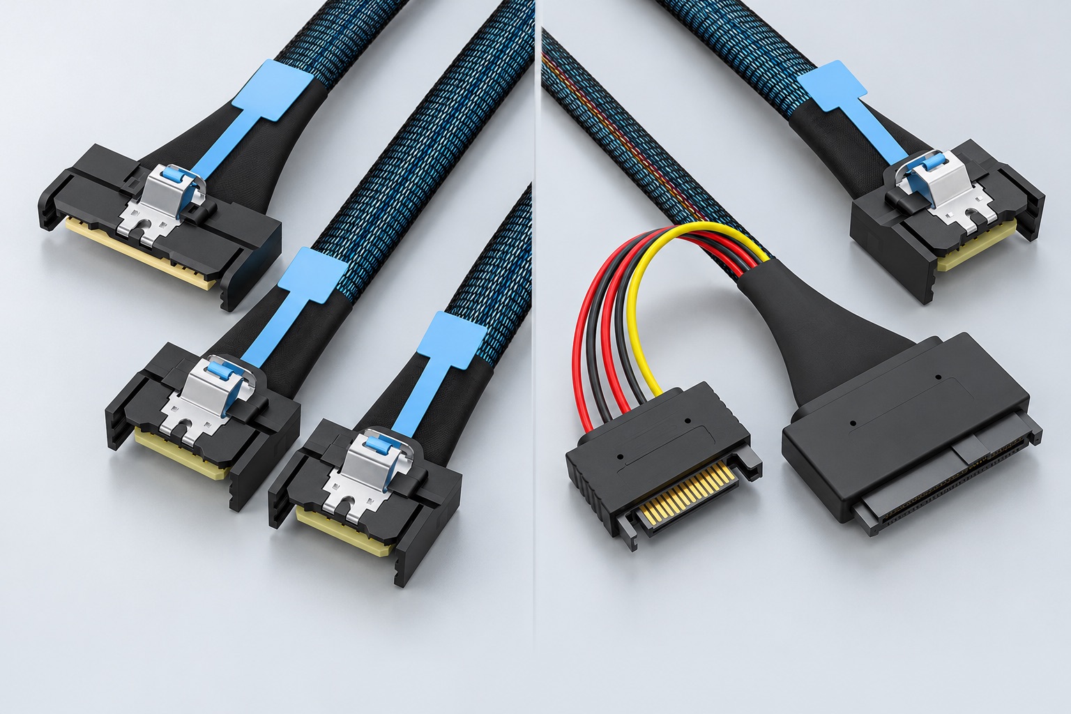
A breakout divides the assembly into separately terminated branches. Give each branch a destination and identifier, then specify its length from a stated measurement point. Avoid describing every leg with one overall length if the receiving ports are spaced apart.
For a PCIe connection intended to serve multiple independent endpoints, check the platform’s supported lane arrangement. Some designs require bifurcation, which divides a link into separately usable groups of lanes. ASUS’s bifurcation support tables show that the available arrangements depend on the board, CPU and slot. A passive breakout does not create support that the platform lacks.
For SATA breakouts, use the forward/reverse connection roles described above. Label the host and drives or backplane in the sketch.
05 / Work through the details
Record the motherboard or controller, port label, backplane and drive models, including hardware revisions. For a replacement, retain the complete cable label and suffixes. Add a connector close-up and a wider installation photograph.
For an equipment family with several backplane options, the server model alone may leave the storage connection ambiguous. Identify the installed backplane rather than choosing from a photograph of a similar chassis.
Record the protocol, lane arrangement and required generation or data rate. State whether the destination is a drive or backplane, and obtain the proposed assembly’s pin assignment and sideband information. Leave unresolved fields explicitly marked as unknown.
Ask the supplier what evidence is available for the required length and configuration. A continuity check can establish whether connections follow a wiring map; it does not by itself demonstrate high-speed operation in the intended system. Agree on the relevant electrical and system validation before a production order.
Measure along the route the cable will actually follow. Include the space needed around fan shrouds, chassis edges and drive cages. State whether the requested length is measured between connector faces, cable exits or another defined point, and have that convention shown on the drawing.
Ask for the cable’s specified bend limits and provide enough room to respect them. Include latch-release access in the clearance review. A plug that fits during initial assembly may still be difficult to service after nearby modules are installed. Check both installation and removal in the intended chassis.
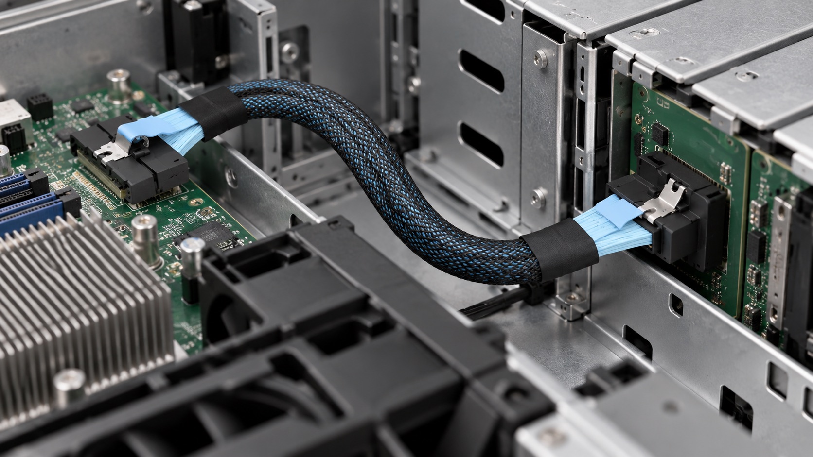
For a power tail, specify its mating connector, required wiring and reach to the power source using the drive documentation. Show the signal and power routes on the same sketch.
Label each branch with its destination port and locate the split relative to the main connector. Each leg needs enough reach to avoid pulling on the others; branch labels should match the chassis port labels.
Review the proposed drawing against the request: endpoints, orientations, overall and branch lengths, pin assignment, power connection and labels. Keep the drawing revision with the selected SKU so procurement and engineering refer to the same configuration. Resolve differences before treating a quotation as technically approved.
Use a sample to check fit, device recognition and operation under the intended workload. Keep the equipment models, firmware, drawing revision and results together. Changes to length, routing or endpoints may require renewed validation; one sample result does not qualify an entire family.
06 / Specify the assembly
A request such as “SlimSAS 8i to two Mini-SAS HD ports” identifies the layout. Add the controller and backplane references, branch destinations and measured route to make it useful for a quotation. Separate fixed requirements, such as mating connectors, from preferences such as sleeve color.
Use the same specification sheet for every offer. Record the proposed drawing revision, length convention, branch arrangement, test evidence and exceptions. An empty performance field remains unknown; it should not become an assumed rating when prices are compared.
If a quotation proposes a variation from the photo, identify the governing drawing. Carry that reference into the purchase order so engineering and procurement order the same assembly.
Retain the approved drawing, cable label, installation photographs and sample results. For the next order, identify changes in the equipment, cable length or route against that record. This gives the review a specific starting point instead of repeating the original selection process.
07 / Apply the checks
These examples from the Renhotec configuration range show how an installation requirement leads to a candidate assembly. Final compatibility depends on the equipment and wiring specified for the order.
| SKU | Listed configuration | Check before ordering |
|---|---|---|
| RHT-726-0001 | MCIO x8, straight to right angle; 30 AWG | Installed exit direction and clearance |
| RHT-726-0003 | MCIO x8 to 2 × MCIO x4 | Platform lane arrangement and branch mapping |
| RHT-726-0006 | MCIO x4 to U.2 SFF-8639; 15-pin power | Host support, drive requirement and power routing |
| RHT-726-1001 | SlimSAS SFF-8654 4i to 4 × SATA | Host/device roles and required breakout wiring |
| RHT-726-1003 | SlimSAS SFF-8654 8i to 2 × Mini-SAS HD SFF-8643 | Backplane implementation and signal mapping |
RHT-726-0001 combines straight and right-angle MCIO x8 ends. It is a candidate when one port has room for a straight exit and the other sits close to an obstruction. The installation sketch should show which way the angled cable must leave the port. Its listed 30 AWG wire gauge does not specify a supported link speed.
For RHT-726-0003, label the two x4 destinations before asking for a quote. Include the host port’s documented lane arrangement and the route to each destination. If the branches must pass on opposite sides of a bracket, show that in the installation sketch. Confirm the available branch lengths and mapping for the proposed assembly.
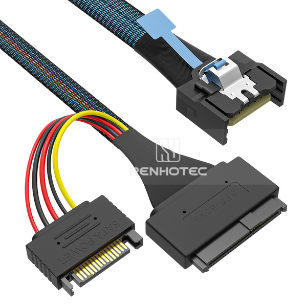
RHT-726-0006 combines an MCIO x4 end, a U.2 SFF-8639 end and a 15-pin power connection. For a direct-drive layout, the signal path runs between the host and drive while the power tail reaches a separate source. Specify those two reaches independently, especially when the drive cage and power connector sit on opposite sides of a bracket.
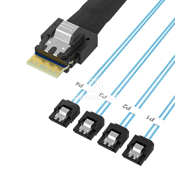
RHT-726-1001 has a SlimSAS 4i end and four SATA ends. Identify the controller or motherboard port and the intended destination of every SATA branch. State the required host-to-device arrangement explicitly. If drive positions are numbered in the chassis, ask how branch identifiers should correspond to them so the installation can be checked without tracing every cable by hand.
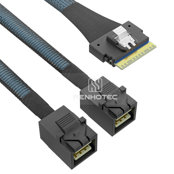
RHT-726-1003 provides a SlimSAS 8i end and two Mini-SAS HD SFF-8643 ends. It is a candidate for a route from one controller port toward two backplane inputs. Label both destination ports on the request; the Broadcom example above explains why this physical arrangement can require different wiring for different storage applications.
08 / Prepare your inquiry
To discuss a Renhotec assembly, include the following information. If a field is unknown, attach the relevant equipment page or a photograph so it can be resolved during the configuration review.
Browse the complete High-Speed I/O range for configuration options, or send your equipment details to Renhotec for review.
Discuss your cable configuration