60A - 120A
125A - 200A
250A - 350A
400A - 480A
Server & storage interconnects
A matching plug is the starting point. Follow the signal path, establish the host’s lane arrangement, then work out how the assembly fits inside the chassis.
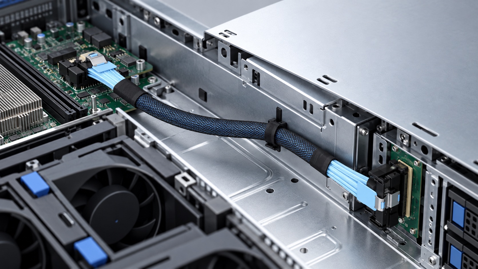
A · Port assignmentThe board documentation defines the protocol and available lanes.
B · Cable routeLeave a gentle sweep and keep the assembly clear of moving parts.
C · Connector exitCheck housing clearance and access to the latch in the assembled chassis.
Only if the host provides the required links. A passive MCIO breakout can route an x8 port to two x4 destinations, but it cannot configure the host or act as a PCIe switch. The port’s lane allocation and the receiving devices determine whether that connection will work.
Start with the motherboard or controller model and the receiving device: a backplane, another board, or a U.2 SSD. Record the port labels printed on both boards. That short description is more useful than ordering by a photograph or by “MCIO PCIe cable” alone.
The server and storage cable selection guide compares MCIO with the other families. For an MCIO route, work from the host’s electrical arrangement to the cable ends and the space available inside the chassis.
MCIO stands for Mini Cool Edge IO. It is a compact interconnect family used for connections inside servers and related equipment. MCIO connectors appear in board-to-board cable routes, storage backplane connections and other high-speed signal paths. A typical assembly combines the connector at each end with the conductors, shielding, termination and retention features needed for its intended channel.
Molex’s Mini Cool Edge family uses a 0.60 mm pitch and includes several circuit counts. Amphenol’s Mini Cool Edge IO family includes SFF-TA-1016 implementations. These describe connector families; the selected cable assembly still needs its own wiring and performance specification.
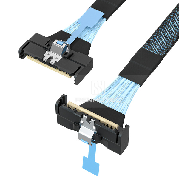
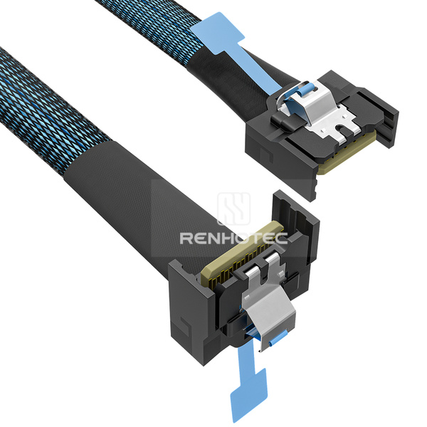
Connector size narrows the choices, but it does not complete identification. A latch, pull tab or familiar cable jacket can help you recognize the family. The connector drawing establishes the mating geometry and contact arrangement. The equipment manual establishes what the port is wired to do.
For a replacement, photograph both ends before removing the existing cable, including its label and the board labels beside the receptacles. If the replacement must exit in a different direction, include a view of the surrounding chassis. A close-up of an isolated plug cannot show the clearance around a fan wall, cover or neighboring port.
For a pinout, use the connector drawing with its stated viewing direction and the selected cable’s end-to-end wiring drawing. The host and destination assignments determine which lanes, reference-clock and sideband connections are required. MCIO is a signal interconnect, not a graphics-card power connector.
For the PCIe arrangements discussed here, x4 and x8 describe four-lane and eight-lane connections. They are not PCIe generation numbers. A wider connection can carry more aggregate traffic at the same generation when the complete system uses that width, but an x8 cable cannot create additional lanes in the host or endpoint.
| Detail | What it tells you | What to use for the decision |
|---|---|---|
| x4 or x8 | The intended lane width of the stated arrangement | Host port allocation, endpoint width and cable lane mapping |
| Contact count | Physical connector contacts, including more than the high-speed lanes alone | Connector drawing and required signal assignment |
| PCIe generation | The signaling generation targeted by the specified implementation | Equipment support and the selected assembly’s qualified conditions |
| One or two destinations | The physical endpoint arrangement | Whether the host exposes the required independent links |
MCIO configurations include 38-contact x4 and 74-contact x8 connections. Amphenol’s connector selector lists those arrangements with sideband signals, and also lists alternative lane uses for the same contact counts. Treat pin count as an identification detail, not a universal pinout or protocol guarantee.
The host determines how its lanes are organized. Eight lanes may be used as one link, or allocated as separate links where the platform supports that arrangement. A passive breakout routes the assigned signals to separate connectors. It does not act as a PCIe switch or configure the host.
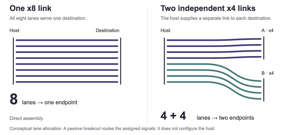
This is why an x8-to-two-x4 cable can be the correct physical shape yet still fail to expose two devices. Before changing the cable, check the exact port’s supported mode. Bifurcation support can depend on the board, processor, occupied slots and firmware configuration. ASUS’s bifurcation compatibility tables show how lane allocation varies by platform. Use the documentation for your own board and port.
Generation is a separate selection field. Amphenol notes that its Gen 5 and Gen 6 designs can retain the interface dimensions while changing internal design. Specify the required generation and assembly qualification; an x4/x8 label is not a speed rating.
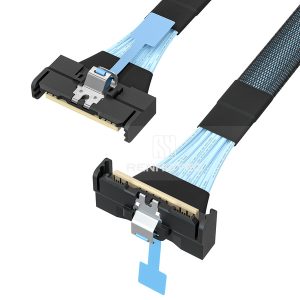
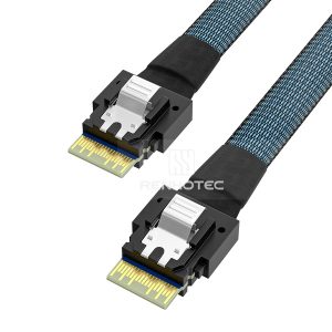
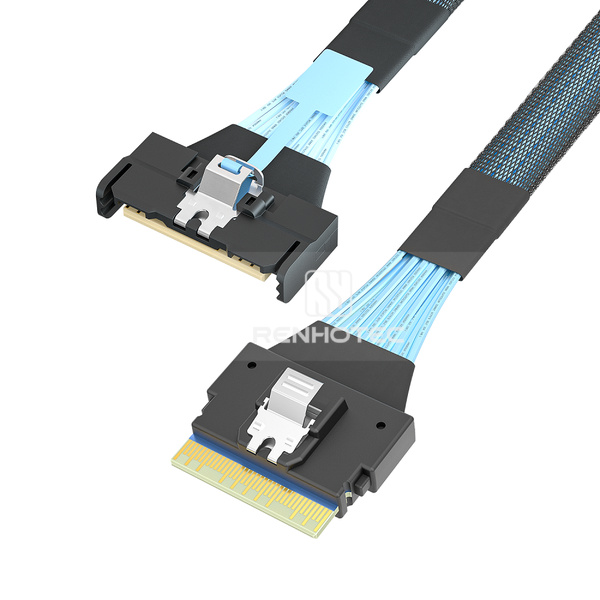
A direct assembly has one MCIO connector at each end. It suits a route where both boards expose the required MCIO interfaces. The two ends can have different mechanical orientations while retaining the specified connection arrangement.
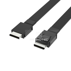
For an x8 route, Renhotec lists straight-to-right-angle, right-exit-to-left-exit and straight-to-straight configurations. For x4, the range includes a straight-to-right-angle option and an MCIO-to-MCIO assembly. Choose the ends against the installed receptacles and nearby structure, rather than assuming that the visually shortest route is the easiest to assemble or service.
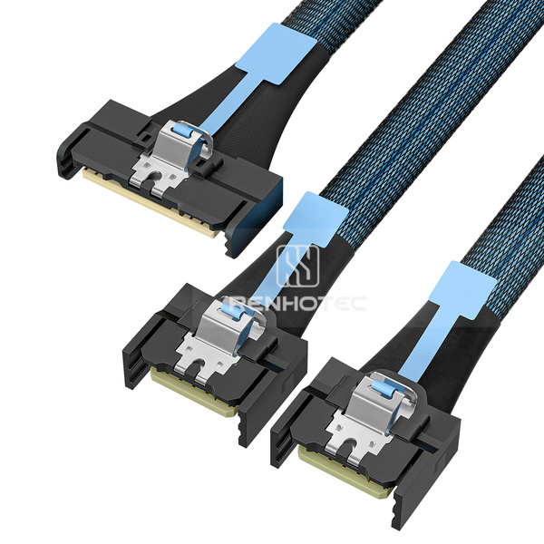
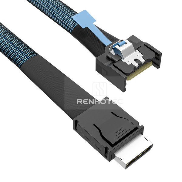
RHT-726-0003 presents one MCIO x8 end and two MCIO x4 ends. It is a candidate when the system requires that physical arrangement. The connection drawing must identify which lanes and supporting signals go to each branch.
Record the destination of each branch by its port label. A cable that reaches both receptacles can still be assembled incorrectly if the two branches are exchanged in a design that assigns them different roles. Branch labels are useful during assembly, replacement and fault isolation.
If two independent PCIe endpoints are connected directly, check how the host supplies the two links. If the destination is a backplane, first identify whether that backplane routes lanes directly or contains active devices. Drive count alone does not describe the upstream connection requirements.
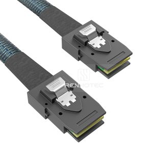
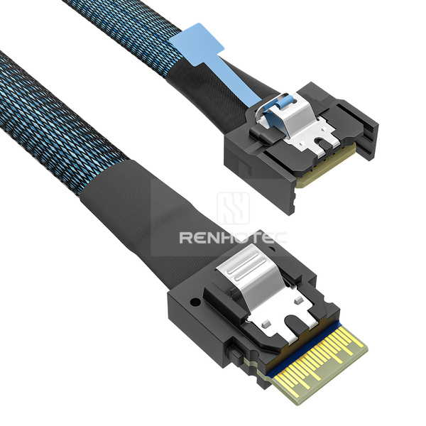
RHT-726-0004 changes the branch connectors to two SlimSAS SFF-8654 4i ends. It combines a breakout arrangement with different connector families. Both decisions matter: the host must provide the intended signals, and each SlimSAS destination must be wired for those signals.
Server manuals can be more useful than generic cable listings at this stage. The ASUS RS700-E11-RS12U manual maps named motherboard ports to named MCIO backplane ports. Follow that level of specificity when documenting your own route. For an OEM replacement, compare the original cable specification as well as the route.
Suppose the host manual assigns two independent x4 links to one MCIO x8 port. If both destinations are MCIO x4, shortlist RHT-726-0003. If both destinations are SlimSAS 4i carrying the corresponding PCIe links, shortlist RHT-726-0004. In either case, label the two destination ports on the route sketch and match that branch assignment to the wiring drawing. If the host exposes only a single unsplit x8 link, neither passive breakout supplies the missing two-link arrangement.
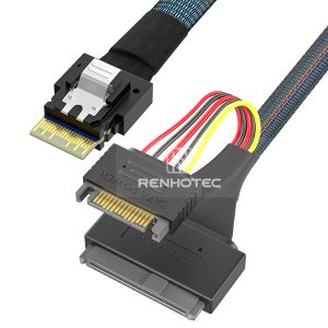
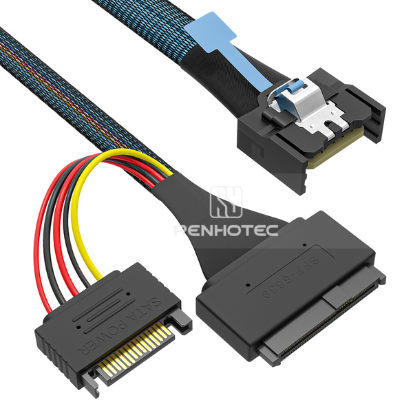
For a direct U.2 drive connection, separate the data path from the power path. The motherboard or controller supplies the intended PCIe connection through the MCIO end. The drive-side SFF-8639 connector mates with the SSD. An assembly with a separate power lead also needs the correct connection to the system’s power supply.
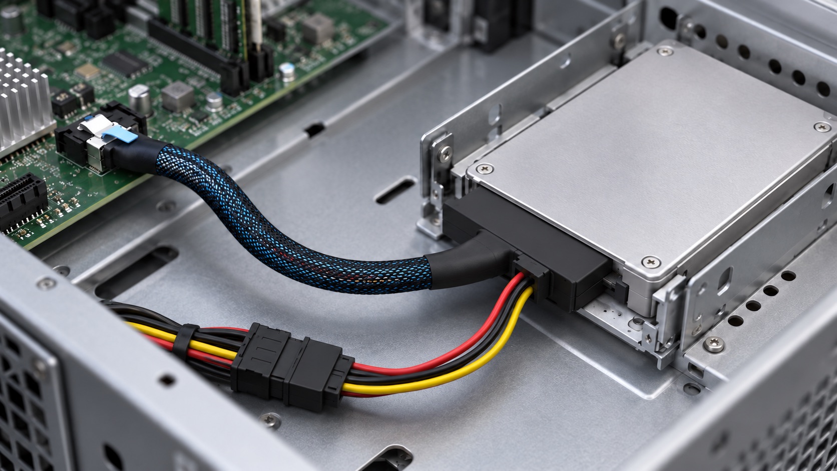
RHT-726-0006 is listed as MCIO x4 to U.2 SFF-8639 with a 15-pin power connector. Specify the drive model and power requirements alongside the signal interface. A SATA-shaped power connection does not turn the drive’s data interface into SATA.
Intel’s U.2 installation instructions show the cable attachment and separate SATA power connection for the Intel configuration described there. Trace both paths in your system, using the selected drive and board documentation.
RHT-726-0006’s U.2 listing does not imply U.3 system compatibility.
Mechanical selection begins at the receptacle. Note its orientation on the board, the space above it and the direction the cable must travel. A right-angle plug can help a cable leave beneath a nearby cover, but its housing may conflict with a neighboring component. A straight plug may offer a cleaner route where space is available above the port.
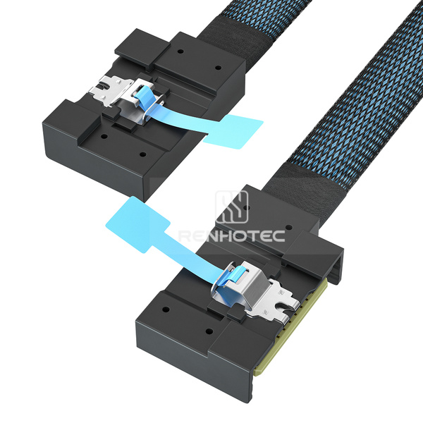
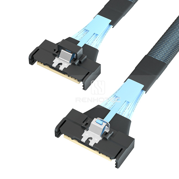
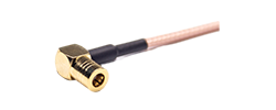
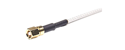
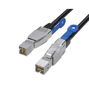
Product photographs shown independently; not a dimensional comparison.
| Configuration | Useful when | Check before selecting |
|---|---|---|
| RHT-726-0001 Straight → right angle | The two ends need different cable exits | Right-angle housing clearance and the direction of the bend |
| RHT-726-0002 Right exit → left exit | The route calls for different lateral exits | The drawing’s viewing convention; “left” changes when the assembly is turned over |
| RHT-726-0012 Straight → straight | Both ends have space for straight exits | Room for the cable sweep beyond each connector |
Measure along the intended cable path, including changes of direction and the access needed to operate the latch. For a breakout, record the main run, split location and each branch separately. Two assemblies with the same overall length may put the split in different places.
Keep the route clear of fan blades, sharp edges and moving service parts. Use the cable assembly’s specified bend and retention requirements instead of a generic minimum radius. Avoid pulling the cable taut between boards or creating a tight bend immediately behind the termination. A little unplanned slack can be as awkward as a short cable if it sits across an airflow opening.
Also record what must be removed to service the cable. Can the latch be reached after the fan wall, cover and neighboring cables are installed? Can a drive carrier be withdrawn without catching a branch? A fit check should include the assembled chassis and the normal service sequence.
Choose the far-end connector from the receiving port, then establish the signal path. A change of connector family is a mechanical routing choice within an appropriately designed system. A passive cable does not translate PCIe into SAS or SATA.
| Connection | Renhotec configuration | Deciding check |
|---|---|---|
| MCIO x4 → SlimSAS 4i | RHT-726-0007 | The SFF-8654 port’s assigned protocol and wiring |
| MCIO x4 → Mini-SAS HD | RHT-726-0008 | The SFF-8643 port’s electrical role; its name alone does not establish the protocol |
| MCIO x4 → OCuLink | RHT-726-0009 | The SFF-8611 connection’s lane and supporting-signal requirements |
| MCIO x8 → SlimSAS 8i | RHT-726-0011 | The full route’s lane allocation and endpoint requirements |
For installed equipment, match the connector at each end. Two MCIO ports call for the appropriate MCIO-to-MCIO arrangement; an MCIO host and SlimSAS destination require a matching mixed-end assembly, such as the x4-to-4i or x8-to-8i configurations above. The two connector families do not mate directly, and choosing one over the other does not upgrade a port’s supported speed.
For a new board, compare the actual receptacle and plug drawings, channel qualification at the required length, exit clearance and sourcing requirements. Neither family name establishes a universal performance winner. The six-family comparison expands the choice to other interfaces.
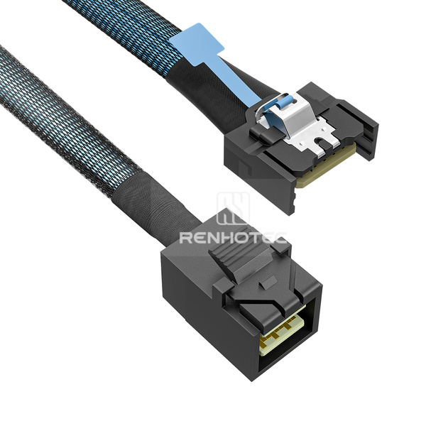
Identify the port’s electrical role from the board documentation.
When comparing quotes, use the same connector arrangement, protocol, lane mapping, length and qualification conditions. Two products described as “MCIO to SlimSAS” may address different routes. An apparently lower price is not a meaningful comparison until those fields agree.
The range covers direct links, breakout assemblies, cross-interface routes and a powered U.2 connection. Use the SKU to identify the arrangement when requesting the drawing and confirming the application.
The listed 30 AWG value applies to RHT-726-0001, RHT-726-0002 and RHT-726-0012. For the other configurations, request the specified wire gauge with the assembly drawing. Wire gauge alone is also insufficient to choose a maximum length or promise a PCIe generation. Those requirements belong in the assembly specification and validation conditions.
A missing device does not isolate the fault to the cable. Work from the system configuration through the physical connection, changing one variable at a time. Follow the equipment’s power-down and service instructions before touching internal connectors; hot-plug behavior is a system feature, not a benefit implied by the MCIO name.
| Observed symptom | Check first | Useful evidence to retain |
|---|---|---|
| Neither endpoint appears | Port protocol, seating, endpoint power and whether the host port is enabled | Board/drive models, port labels and firmware settings |
| Only one breakout device appears | Host link allocation, branch assignment and the second destination’s power | Which branch and destination work in a controlled substitution |
| A U.2 SSD remains undetected | Separate power connection, PCIe route and drive/host support | Drive model, power arrangement and the exact cable specification |
| Link width or generation is below expectation | Host/endpoint limits, lane allocation, firmware and qualified cable/channel conditions | Negotiated link information and repeatable test conditions |
| The cable will not fit with the cover installed | Exit direction, connector height, split location and routing space | Photographs with dimensions and the required service clearance |
If the equipment maker provides an approved cable arrangement, establish a baseline with that configuration. A substitution test is useful only when the relevant wiring, endpoints and operating conditions are understood. Do not reconnect a superficially similar assembly to a different protocol port just to see whether it works.
Detection confirms that a device has been enumerated in that configuration. It does not establish sustained throughput, stability under load, serviceability or support for every populated bay. Record the negotiated link width and generation, then use the platform’s recommended diagnostics and a representative workload.
For a new assembly, keep the agreed acceptance conditions with the sample record: host and endpoint models, firmware, cable length, lane layout and the test performed. This makes a later cable revision or supplier comparison traceable. If the system changes, identify which of those conditions needs to be checked again.
A useful request connects a physical arrangement to a defined system. Supply the port and equipment details early, especially when the far end uses another connector family. If a field is undecided, state the intended requirement rather than choosing a value from a similar-looking product.
Information for an MCIO cable inquiry.
“We need one MCIO x8 end connected to two MCIO x4 ports. Our platform documentation specifies two independent x4 links on this host port. The attached sketch identifies the two destination ports, branch labels, route lengths and connector orientations. Please review RHT-726-0003 against the attached wiring requirements and advise the assembly specification and sample validation requirements.”
The same structure works for a replacement: include the original part number and drawing, explain what is changing, and show the required route. If only the exit direction changes, call that out explicitly so the electrical requirements remain clear.