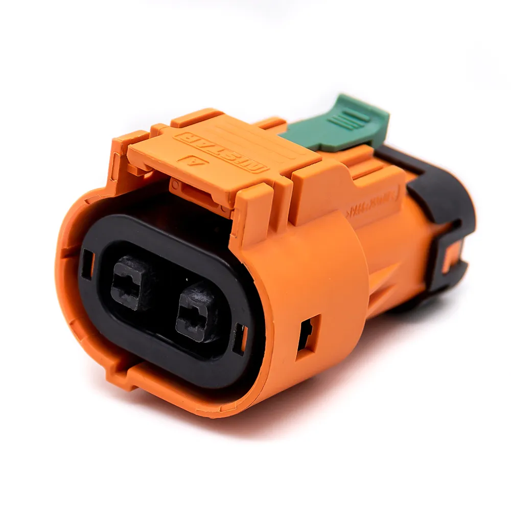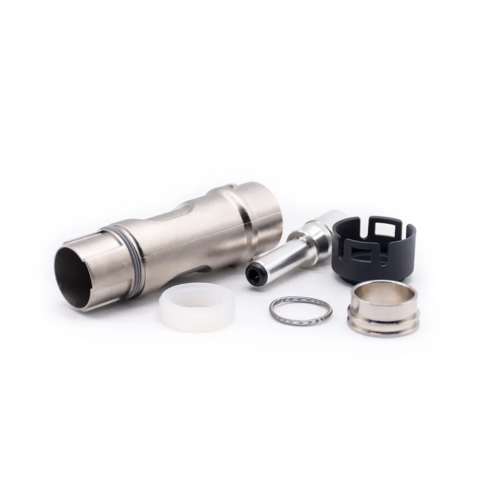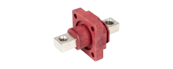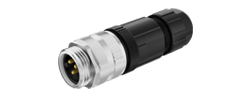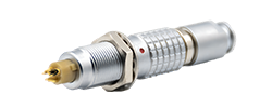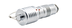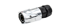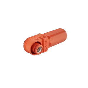
60A - 120A
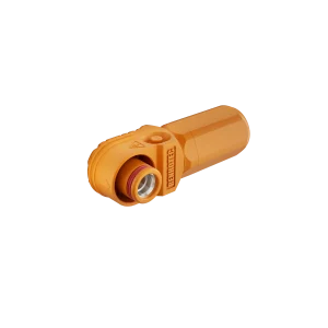
125A - 200A
250A - 350A
400A - 480A

Energy storage · product application
Check whether this orange 8 mm receptacle fits your panel and rear termination, using its published dimensions and a worked layout example.
RHT-S008-T02-OG is an orange, panel-mount energy storage receptacle with an 8.0 mm interface and an M8 external threaded rear terminal. Renhotec lists a 200 A rated current. Its application is a fixed connection through an enclosure panel, where the mating cable connection is accessible from one side and the internal conductor attaches at the rear. Housing color alone does not assign circuit polarity; identify polarity in the system documentation.
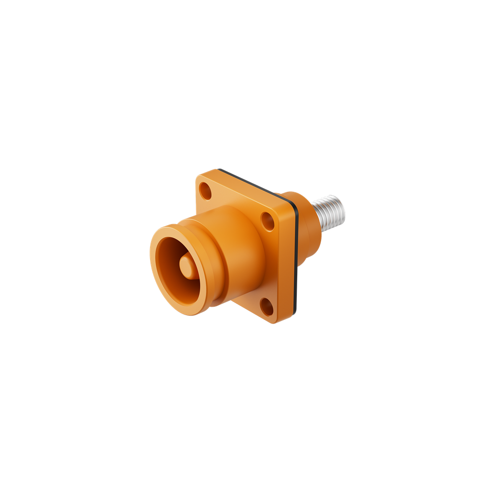
RHT-S008-T02-OG
The flange establishes the panel attachment. The rear terminal needs conductor, hardware and tool clearance inside the enclosure.
A fixed panel receptacle places the removable cable interface at the enclosure boundary and the internal conductor joint behind it. The external M8 terminal is useful when the proposed rear termination is designed around a threaded stud. If the internal harness requires an internal-thread or cable-tail termination, start with that alternative instead.
The public Renhotec drawing identifies the S008.T02 family, including the orange variant, at revision A/0 dated July 15, 2023. It separates the receptacle flange dimensions from the recommended panel opening. That distinction matters when preparing a panel drawing.

| Drawing feature | Nominal value | Use in the layout |
|---|---|---|
| Flange outside size | 30 × 30 mm | Space occupied on the panel face |
| Mounting-hole centers | 22 × 22 mm | Position of the four fasteners |
| Flange holes | 4 × Ø4.3 mm | Holes in the connector flange |
| Recommended panel holes | 4 × Ø4.4 mm | Panel mounting-hole callout |
| Panel center opening | Ø20 mm | Clearance opening for the body |
| Rear terminal | M8; 13 mm dimension shown | Review the terminal and hardware envelope |
| Overall length | 51 mm reference | Initial enclosure space planning |
Do not substitute the flange-hole diameter for the panel-hole callout. Do not use the 51 mm reference dimension as the finished assembly envelope: the connected plug, internal conductor and terminal hardware add space. The drawing’s tolerances and the approved panel construction remain part of the mechanical definition.
Outside the enclosure
Allow space for the specified plug, cable exit and release action. Nearby panels or cable bundles must not prevent full engagement or planned servicing.
At the flange
The drawing includes a square gasket. Match the panel surface, opening, mounting hardware and seal arrangement to the assembly instructions.
Inside the enclosure
Reserve space for the selected conductor termination and the tool used to tighten it. Determine the approved hardware stack and tightening value before assembly.
Along the conductor
Support the internal conductor so it does not twist or bend the receptacle terminal. Review clearance from adjacent live parts and enclosure metal under the system’s electrical design requirements.
A useful fit review shows the receptacle, panel thickness, gasket, fasteners, mating plug and rear conductor in the same assembly drawing. Reviewing only the connector’s outline misses the interfaces where installation problems often occur.
The M8 terminal designation does not specify a tightening torque, conductor size or lug design. Those must come from the approved termination and assembly instructions; a general M8 fastener torque chart does not qualify an electrical joint.
The product page gives a 200 A rated current, identifies the housing as nylon and lists panel mounting. The published drawing provides additional family-level electrical and mechanical information. Application approval needs the exact supplied variant and operating conditions.
| Requirement | Available reference | Application review |
|---|---|---|
| Current | Product page lists 200 A | Duty cycle, ambient temperature, conductor/termination and applicable derating |
| Voltage | A/0 family drawing lists 1500 V DC | Applicability to the supplied variant and the complete system’s insulation requirements |
| Sealing | A/0 drawing lists IP67 and a gasket | Required mated/unmated condition, panel seal, assembly method and test conditions |
| Mating part | 8.0 mm receptacle family | Explicit mating plug part number and approved combination |
| Rear connection | M8 external terminal | Conductor termination, hardware stack and assembly torque |
These checks prevent a component rating from becoming an unsupported claim about the finished enclosure. The operating current and thermal behavior depend on the entire current path. A panel gasket also does not establish sealing for every installation or disconnected state.
The cited listing and outline drawing do not establish load-breaking capability. Use the system isolation procedure; obtain an explicit switching rating if the application requires disconnection under load.
Use the supplier’s applicable declarations and test information when qualification requires them. A certificate appearing beside a product is not, by itself, a complete statement of the assembled system’s conformity.
Suppose a panel design reserves a 32 × 32 mm square for the receptacle face, with a Ø20 mm opening and four Ø4.4 mm holes on 22 × 22 mm centers. These are hypothetical design inputs for checking the published nominal geometry, not a tested installation.
Face envelope
A centered 30 mm flange leaves 1 mm on each side of the reserved square. The outline fits nominally, but that margin alone does not establish fastener or service-tool access.
Hole pattern
The proposed pattern and diameters match the nominal panel callouts. A panel with 24 mm centers would require a different pattern or a different connector.
Decision: retain RHT-S008-T02-OG as a mechanical candidate for this proposed position, then check tolerances, panel thickness, gasket compression and access in the complete layout. The 51 mm reference length excludes the space added by the mating plug and rear termination; the outline drawing alone cannot approve enclosure depth.
Now check the current path using the ratings table above. A nominal mechanical match does not establish the required operating current, thermal performance or insulation clearances. Specify the approved plug, rear conductor termination and hardware before reviewing a complete sample assembly.
For this configuration, open the RHT-S008-T02-OG product page and the S008.T02 drawing together. If the rear termination or panel position differs, compare other energy storage connector configurations before modifying the panel.
Reference RHT-S008-T02-OG and attach the panel layout, mating-plug requirement and rear termination concept. Include operating conditions and any qualification requirements so the review covers the whole connection.