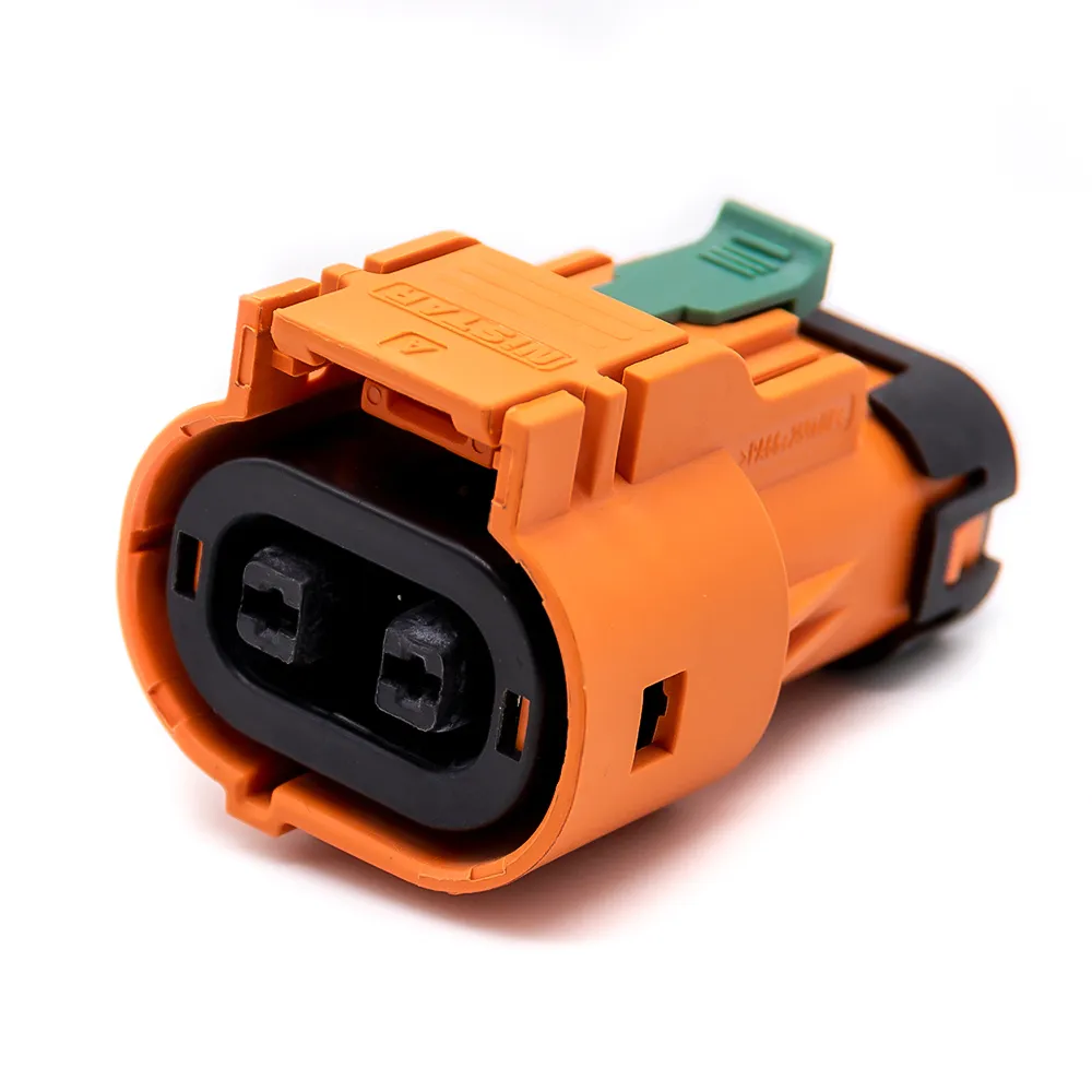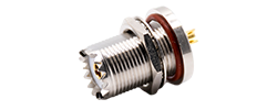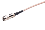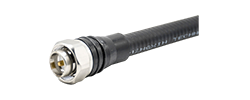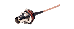
60A - 120A
125A - 200A
250A - 350A
400A - 480A
ON THIS PAGE
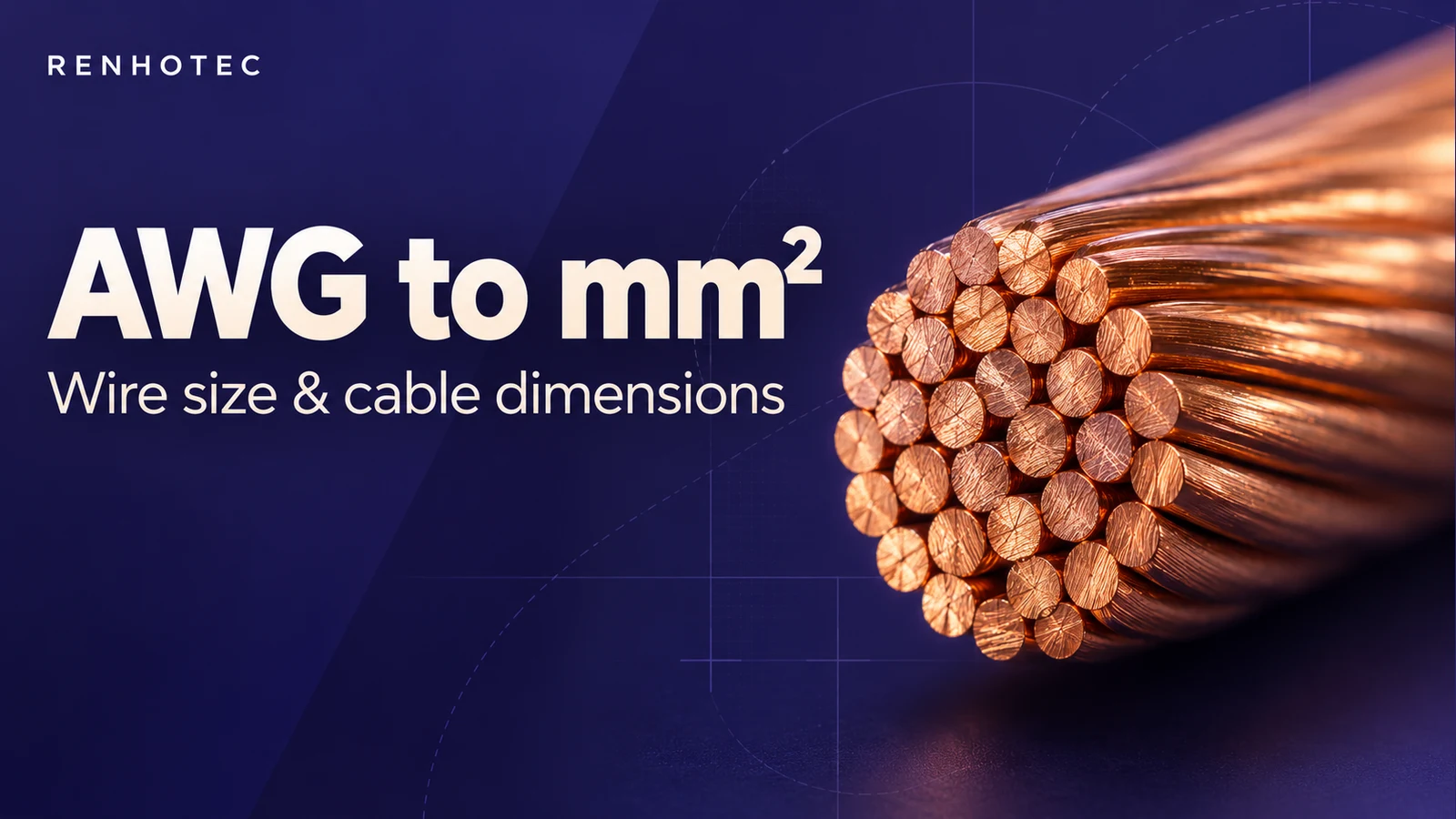
Convert wire gauge to conductor area. Then tell that number apart from the diameter of a strand, an insulated core and the complete cable.
A 24 AWG solid round conductor has a reference area of about 0.205 mm² and a diameter of about 0.511 mm. Neither number gives the outside diameter of an insulated cable. Use the converter for geometric reference values, and the sections below to read a real cable specification.
Look up a gauge, or compare a cross-sectional area with the two neighboring AWG sizes. The supported range is 30 AWG to 4/0 AWG.
Use a decimal point, for example 0.25 or 2.5.
Geometric conversion only. These results do not specify cable OD, current capacity or an approved substitute.
For gauge number n, the reference diameter is d = 0.127 × 92((36 − n) / 39) in millimetres. The circular area is A = πd² / 4 in mm². Use n = 0, −1, −2 and −3 for 1/0, 2/0, 3/0 and 4/0 respectively.
The progression is described in NBS Handbook 100, Copper Wire Tables, section 2.2. Results here are calculated before rounding and displayed to four significant figures. Percentage differences use the entered area as the denominator. An exact geometric match is shown as one result; otherwise, both neighboring sizes are shown. A rounded input can sit slightly above or below a nominal value.
These are geometric reference values, not manufacturing tolerances. Actual stranded conductors and nominal metric cable specifications require their own product data.
As the AWG number gets smaller, the conductor gets larger. The zero sizes continue that sequence: 1/0, 2/0, 3/0, then 4/0. This table uses AWG, not SWG or another gauge system.
Area excludes insulation. Diameter refers to a solid round conductor. Scroll inside the table for all sizes.
| AWG | Conductor area mm² | Solid conductor diameter mm |
|---|---|---|
| 30 | 0.05093 | 0.2546 |
| 29 | 0.06422 | 0.2859 |
| 28 | 0.08098 | 0.3211 |
| 27 | 0.1021 | 0.3606 |
| 26 | 0.1288 | 0.4049 |
| 25 | 0.1624 | 0.4547 |
| 24 | 0.2047 | 0.5106 |
| 23 | 0.2582 | 0.5733 |
| 22 | 0.3255 | 0.6438 |
| 21 | 0.4105 | 0.7229 |
| 20 | 0.5176 | 0.8118 |
| 19 | 0.6527 | 0.9116 |
| 18 | 0.823 | 1.024 |
| 17 | 1.038 | 1.15 |
| 16 | 1.309 | 1.291 |
| 15 | 1.65 | 1.45 |
| 14 | 2.081 | 1.628 |
| 13 | 2.624 | 1.828 |
| 12 | 3.309 | 2.053 |
| 11 | 4.172 | 2.305 |
| 10 | 5.261 | 2.588 |
| 9 | 6.634 | 2.906 |
| 8 | 8.366 | 3.264 |
| 7 | 10.55 | 3.665 |
| 6 | 13.3 | 4.115 |
| 5 | 16.77 | 4.621 |
| 4 | 21.15 | 5.189 |
| 3 | 26.67 | 5.827 |
| 2 | 33.63 | 6.544 |
| 1 | 42.41 | 7.348 |
| 1/0 | 53.48 | 8.251 |
| 2/0 | 67.43 | 9.266 |
| 3/0 | 85.03 | 10.4 |
| 4/0 | 107.2 | 11.68 |
Values use the formula above. ASTM B258 covers nominal diameters and areas of solid round AWG conductors. Use the cable specification for actual construction and tolerances.
A cable drawing may give several sizes in millimetres, alongside a conductor size in mm² or AWG. They refer to different boundaries.
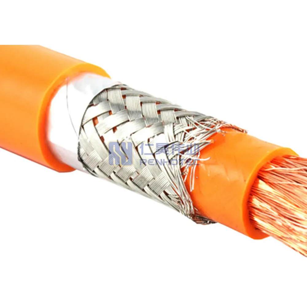
The outer jacket surrounds four insulated cores. Each core contains a stranded conductor.
Two cables with the same conductor size can have different overall diameters because their insulation, core count, screening and jacket constructions differ. Measuring the jacket with calipers does not reveal the AWG inside it.
A conversion table and a cable catalog may be answering different questions. One gives the geometric area associated with a gauge; the other may list nominal product sizes or compare sizes against electrical requirements.
≈ 0.2047 mm²
A separate product designation
LAPP’s T16 technical table separates geometric conversion from metric nominal sizes that meet stated electrical requirements. Its two columns therefore need not contain the same number. That comparison is not permission to substitute any cable with a nearby nominal area.
If a drawing specifies 24 AWG, keep that requirement attached to the wire construction and applicable specification. If it specifies 0.25 mm², select against that requirement. A dual-marked product should be assessed using its own documentation, including conductor resistance and termination requirements; the slash between two designations is not necessarily an exact mathematical equality.
Metric standards also have defined scopes. IEC 60228:2023 covers nominal cross-sections from 0.5 to 3,500 mm² for conductors in power cables and cords, and excludes telecommunication conductors. Do not assume every smaller metric wire size falls within that standard.
For a geometrical example, take seven round strands, each 0.20 mm in diameter. Their combined metal area is approximately 0.220 mm². A solid round wire with that area is about 0.529 mm in diameter.
For equal-diameter circular strands, use A = strand count × π × strand diameter² / 4. Here, 7 × π × 0.20² / 4 ≈ 0.220 mm². Applying the solid-circle formula to the entire 0.600 mm envelope would count the gaps as metal.
7 × 0.20 mm describes seven strands of 0.20 mm diameter when the column is explicitly a stranding specification. 7/32 may instead mean seven strands of 32 AWG; read the manufacturer’s column heading. Neither notation means a seven-core cable.
4 × 0.34 mm², in a cable construction description, normally identifies four conductors of nominal 0.34 mm² each. It does not mean one 1.36 mm² conductor, and it does not specify the jacket diameter.
A real example shows why this distinction matters. TE lists 55FA0514-24-7L as 24 AWG with 19 strands, a conductor diameter range of 0.55–0.63 mm and an outside cable diameter of 1.14 mm. Those are separate fields on that product page; the calculator’s approximately 0.511 mm solid-wire reference does not replace either diameter.
A conductor can fit a terminal while its cable jacket is too large for the entry. The reverse is also possible. Both interfaces need to match.
Check the allowed wire size and conductor construction. For a crimp contact, use its specified wire, tooling and crimp requirements. For a screw terminal, check permitted solid or stranded conductors and any ferrule requirements.
Compare: AWG / nominal mm², construction and termination instructions.
Compare the actual cable OD, including tolerance, with the stated clamping range. Where individual wire seals are used, their fit depends on the insulated core diameter instead.
Compare: cable OD or insulated core OD with the applicable seal or clamp range.
For example, a Renhotec M12 screw-contact field-assembly plug has both a wire termination and a cable entry. Check the selected configuration’s drawing for each. The PG7 designation alone does not supply a conductor size or the complete cable-clamping range.
When preparing a cable-and-connector specification, carry over the cable part number, conductor size and construction, insulated core diameter where relevant, and overall cable diameter with tolerance. This lets the two interfaces be checked against the same actual cable. Renhotec’s drawing and catalog downloads provide a starting point for identifying the selected product.
A wire-size conversion cannot determine how much current an assembly may carry. Conductor material, insulation temperature rating, ambient temperature, grouping and installation conditions all matter. The connector’s rating and the applicable wiring rules also need to be satisfied.
For a longer cable, check voltage drop using the specified conductor resistance and circuit length. A wire that meets a thermal requirement may still produce too much voltage drop for the load. Conversely, a larger conductor may fall outside a contact’s permitted termination range.
Use this page to translate the size and identify the measurement. Use the selected wire and connector documentation to establish the permitted assembly.