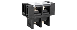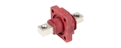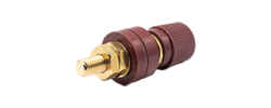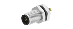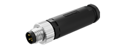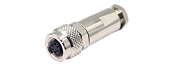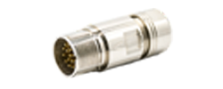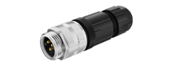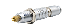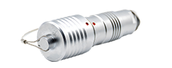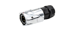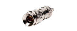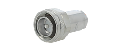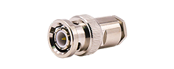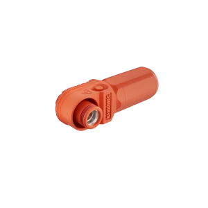
60A - 120A
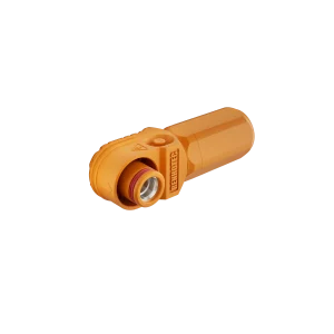
125A - 200A
250A - 350A
400A - 480A
RENHOTEC PRODUCT GUIDES / READING TECHNICAL DOCUMENTS
A practical guide with examples: find the right variant, read the conditions behind its ratings, and turn the drawing into a useful check.
A connector rated at 4 A may look suitable for a 3 A circuit. Before choosing it, you still need to know which contact arrangement the figure covers, how the contacts are loaded, and what temperature conditions apply. The same reading habit matters for voltage, sealing and mechanical fit.
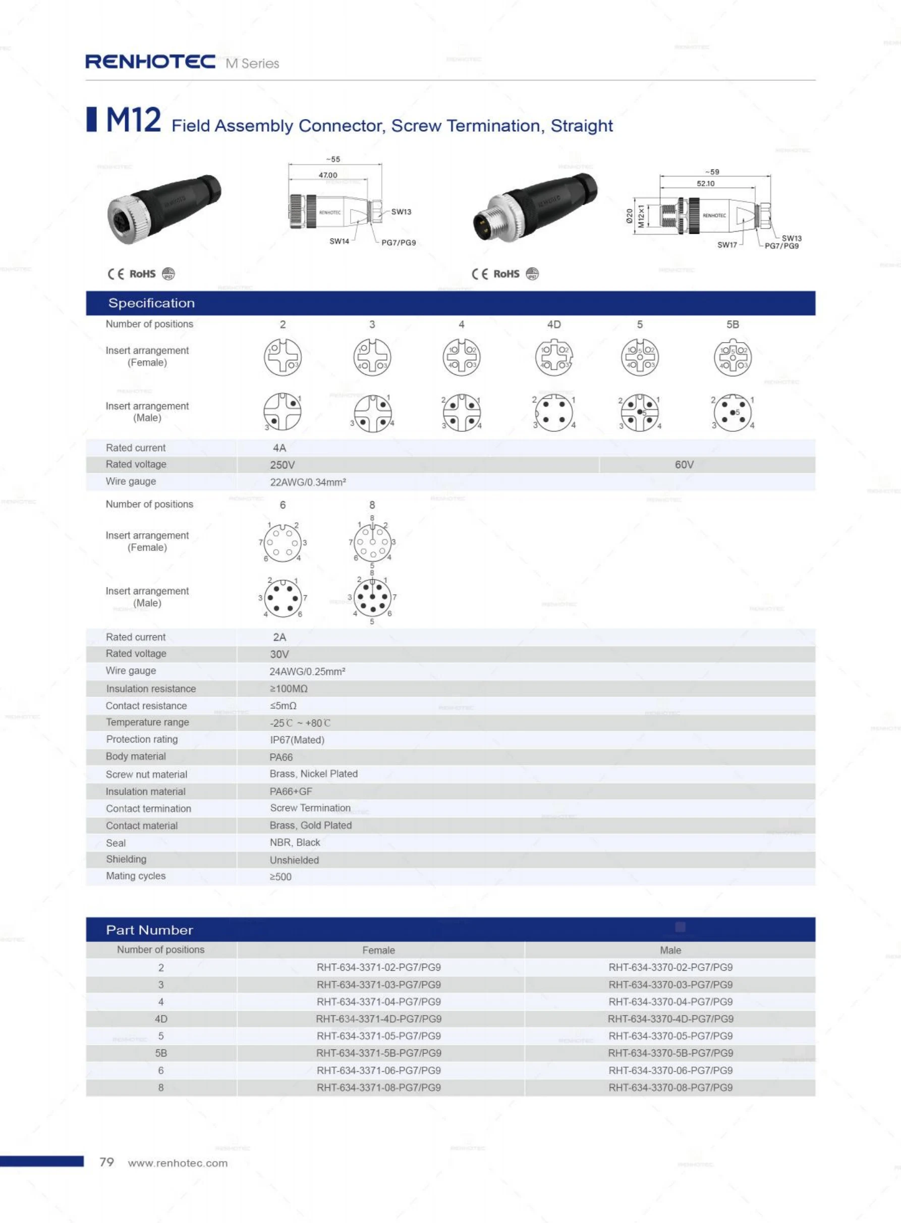
Start with the exact part and document. Locate its specification row, read each value with its qualifiers, then compare the drawing and ratings with your application. This guide follows that sequence using a Renhotec M12 catalog page and a separate Renhotec panel-connector drawing.
01 / THE DOCUMENT IN FRONT OF YOU
A family name such as M12 narrows the search, but leaves many choices open. Contact arrangement, termination, orientation and cable-entry configuration can differ within that family. Record the part number as it appears in the ordering table, including the suffixes that select your version.
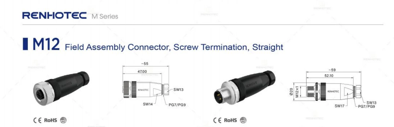
The example page covers straight, screw-terminated M12 field assembly connectors. It has separate female and male ordering columns. It does not describe every M12 cable assembly or every termination style. The neighboring page covers solder-cup versions, so even a one-page navigation error can change the product being selected.
These may be separate files or sections of the same document. Keep their identifiers together. A download date records when you obtained a file; it does not establish its engineering revision. If the catalog and a part-specific drawing disagree, resolve the difference with the supplier before releasing the order or design.
For this example, the ordering table lists the four-position male version as RHT-634-3370-04-PG7/PG9. The website separately lists RHT-634-3370-04-PG7. Select the required cable-entry option explicitly; do not copy a catalog expression containing alternatives into an order without resolving it.
02 / FOLLOW THE COLUMN
Specification tables often save space by merging cells across several variants. Read the column heading first, then trace the applicable cells down the table. When the layout restarts with another group of contact counts, start again from that group’s heading.
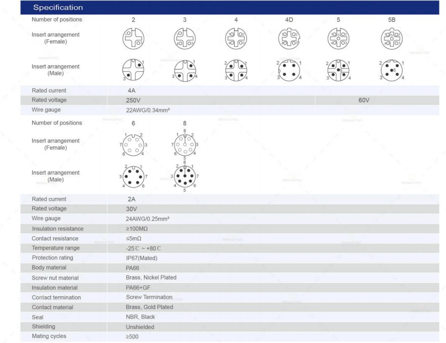
The columns marked 4 and 4D are separate arrangements. A contact count alone does not select the interface.
The four-position column uses the upper rating block. Eight positions uses the lower block.
The protection entry includes “Mated.” The resistance rows include inequality symbols.
| Field | Column marked 4 | Column marked 8 |
|---|---|---|
| Rated current | 4 A | 2 A |
| Rated voltage | 250 V | 30 V |
| Wire gauge, as printed | 22 AWG / 0.34 mm² | 24 AWG / 0.25 mm² |
The four-position value cannot be carried over to the eight-position version. Likewise, copying “250 V” into a general description of all M12 connectors would erase the distinction that the table makes.
The wire-gauge entries above are reproduced as printed, not as exact conversions between AWG and mm². They do not state a complete permitted conductor-size range or establish that a cable with that conductor size fits the gland. Conductor size and cable outside diameter describe different parts of the assembly.
The voltage row uses V without specifying AC or DC. For an AC or DC circuit, obtain the applicable rating and conditions for the exact configuration. A qualifier shown on another catalog page or a similar-looking connector does not establish the rating for this one.
03 / THE SMALL WORDS MATTER
A useful specification entry contains more than a number. Keep the parameter name, value, unit, applicable variant and condition together. Symbols such as ≤ and ≥ are part of the requirement; removing them changes its meaning.
CONTACT RESISTANCE
≤ 5 mΩ
An upper limit on the listed resistance.
INSULATION RESISTANCE
≥ 100 MΩ
A lower limit on the listed resistance.
Read “typical” differently from a stated minimum or maximum: it describes a representative value under the source’s conditions, rather than automatically establishing a guaranteed acceptance limit. Also look for “initial,” “after test” or a named test sequence. Values taken at different stages should not be treated as interchangeable.
Check the loaded-contact arrangement, ambient temperature and permitted temperature rise. If a derating curve is supplied, read its axes, the tested configuration and any wire-size notes before using a point on it. A curve for one configuration is not a correction factor for every product in the family.
The example shows why quoting only a headline current can mislead. It does not establish a universal derating percentage. For the Renhotec catalog example, the page’s temperature range and current rating alone do not show the allowable current at every temperature in that range.
Working voltage describes intended continuous use within the specified conditions. A dielectric-withstand entry describes a test, including its applied voltage and duration where stated. Breakdown voltage describes failure. A higher test voltage should not replace the working-voltage entry in your application comparison. The Power and Voltage Rating paper hosted by Samtec explains these distinctions; its numerical rating methods should not be applied to an unrelated product.
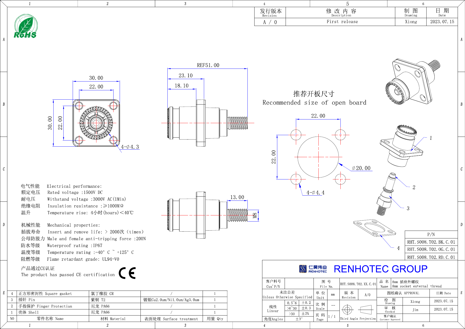
The separate Renhotec S008 drawing used below lists a rated voltage of 1500 V DC and a withstand voltage of 3000 V AC for 1 minute. These entries answer different questions. The second does not authorize continuous operation at 3000 V AC. Read the drawing.
The M12 catalog’s protection entry is IP67 (Mated). The word in parentheses matters: this entry does not establish the same protection for an open connector. Use the appropriate assembly and mating instructions when assessing the completed connection.
Temperature labels also need an object. Phoenix Contact product 1329943, for example, separates plug/socket conditions from fixed and flexible cable-installation conditions. A cable temperature limit should not be promoted to a limit for the complete connector assembly. See its environmental and cable data.
For mechanical life, record the stated cycle count and any test conditions. The M12 page lists at least 500 mating cycles; it does not give a service life in years. A usage schedule alone cannot account for the environment, handling or the acceptance criteria used in the test.
04 / READ THE GEOMETRY
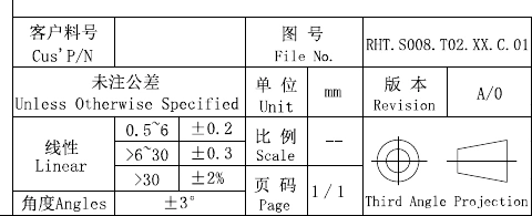
Begin with the title block: part or drawing number, revision, units and general tolerances. Then identify what each view depicts. A connector outline, a recommended panel cutout and a mating-part drawing serve different purposes, even when their dimensions look similar.
The following example is a separate product: the Renhotec S008 panel receptacle associated with RHT-S008-T02-OG. It is useful because its drawing places the component and the recommended panel opening side by side.
4 × Ø4.3 mm
Holes in the component flange
4 × Ø4.4 mm
Holes in the recommended panel pattern
The flange is shown as 30 × 30 mm. The mounting-hole centers are 22 × 22 mm, and the recommended central panel opening is Ø20 mm. Using the flange’s Ø4.3 mm callout as the recommended panel-hole size would copy a dimension from the wrong view.
The title block gives a general linear tolerance of ±0.3 mm for dimensions greater than 6 mm and up to 30 mm, unless otherwise specified. On that basis, an unqualified 22.00 mm dimension corresponds to 21.70–22.30 mm. A specific tolerance attached to a dimension takes precedence over the general entry.
Inspect the original title blockThis arithmetic reads one dimension; it does not complete an assembly fit check. That also needs the relevant panel, hardware, mating component and clearance requirements. Do not use a screen ruler on a PDF image to replace a dimension that the drawing does not specify.
Before following pin numbers, find out whether the view is from the mating face or the termination side, and whether it shows pins or sockets. A view from the other side changes the apparent arrangement. Use the drawing’s orientation reference or keying feature to align the view.
An insert-arrangement picture locates contacts. It does not by itself define what signal reaches each contact in a cable assembly. For wiring, use the applicable pin-assignment or wiring drawing with both ends identified. The M12 catalog image above is used to identify table columns, not as an installation wiring instruction.
05 / PUT THE READING TO WORK
Consider an illustrative request for an eight-position, straight M12 field assembly connection with screw termination. It calls for 3 A on each loaded circuit at 60°C and requires IP67 while the connection is open. Compare that request with the eight-position group on catalog p. 79.
8 positions · straight · screw termination
3 A per loaded circuit at 60°C · IP67 when unmated
| Requirement | What the source says | Decision at this stage |
|---|---|---|
| Eight positions, straight, screw termination | The page heading and eight-position column describe these features. | Listed matchContinue with the required gender and cable-entry option. |
| 3 A per loaded circuit | The eight-position group lists 2 A rated current. | Outside the listed ratingThe 4 A entry in the upper group cannot qualify this version. Seek a suitably rated configuration. |
| Required load at 60°C | A −25°C to +80°C temperature range is listed, but no current-versus-temperature curve is given on this page. | Load conditions neededThe temperature range alone does not approve the requested electrical load at 60°C. |
| IP67 while unmated | The stated protection is IP67 (Mated). | Not established by this entryFind a product or specified protective arrangement with documented protection in the required state. |
The current requirement already prevents accepting this catalog entry as the proposed solution. Missing information about temperature or open-connector protection does not erase that mismatch. Nor should “not established” be recorded as proof that the manufacturer has no suitable alternative.
06 / GET THE RIGHT NEXT DOCUMENT
Give the supplier the part or catalog entry, your actual operating conditions and the question that remains. A request tied to a document and a requirement is easier to answer than “please send all technical information.”
We are reviewing the eight-position, straight screw-termination M12 group on catalog page 79. Our circuits require 3 A at a 60°C ambient temperature, with all used contacts loaded simultaneously. The page lists 2 A, so we need a different configuration that meets this load. Please identify the complete ordering code and provide its applicable current/temperature data. We also need documented IP67 protection while disconnected; please specify the connector or protective arrangement and its assembly instructions.
For a mechanical question, attach the mating-part or panel drawing and identify the dimension involved. For an electrical question, include the operating voltage, load pattern and temperature conditions. Send the relevant configuration rather than an unrelated family photo.
Use the catalog page for the product group, then request the complete configuration and its applicable drawing.