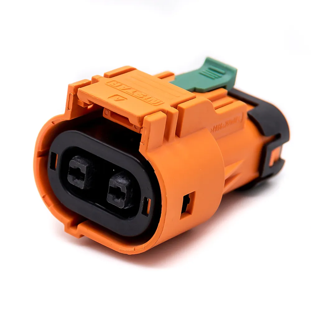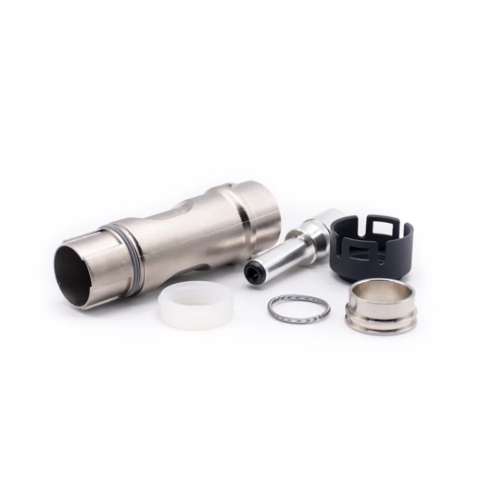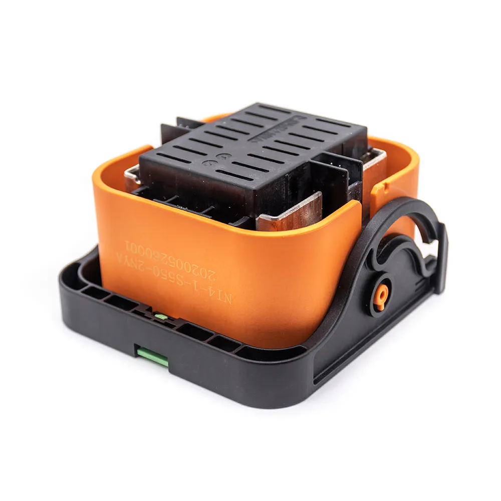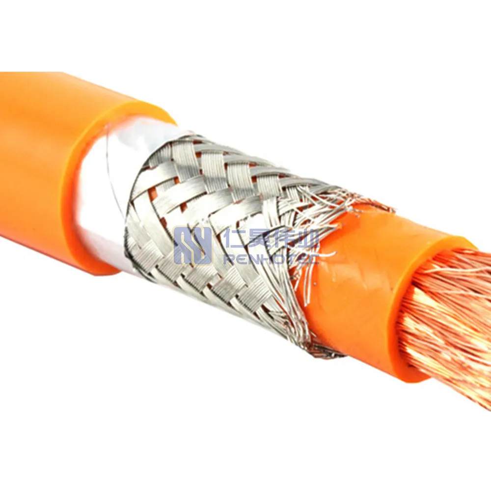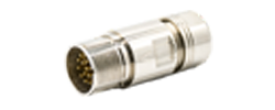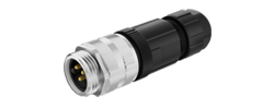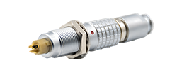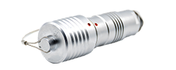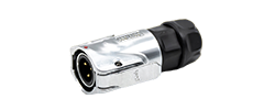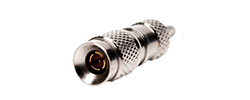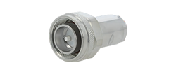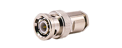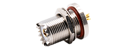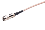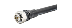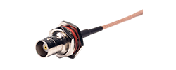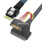
60A - 120A
125A - 200A
250A - 350A
400A - 480A
An illustrated glossary of the parts, properties and processes behind electrical connections.
A contact carries current.
A housing locates it.
A rating describes its limits.
Connector language mixes part names, manufacturing methods and measured properties. A “socket” might mean a contact or a complete connector; “voltage” might refer to normal operation or an insulation test. Start with the term you need, or follow the seven topics from physical structure to signal behavior.
66 topic entries · A–Z
No matching term. Try another spelling or browse the topics below.
Follow the path from the mating face to the cable. Contacts carry current; the surrounding parts locate, protect and support them.
A component that joins electrical paths between wires, cables, circuit boards or equipment. Many connectors make a separable connection; the word may refer to one half or to a mating pair. This glossary focuses on electrical connectors, including RF and high-speed types.
A contact is the conductive part that engages its mate. A terminal is a conductive connection point or part used to terminate a wire or circuit. The names overlap in catalogs: a crimp contact can have a mating end and a wire-terminal end.
A pin contact enters a socket contact; the socket grips the pin with a conductive contact surface. These are often called male and female contacts. The shape of the outer shell alone does not tell you which contact is inside.
Scroll sideways to see the full diagram ↔
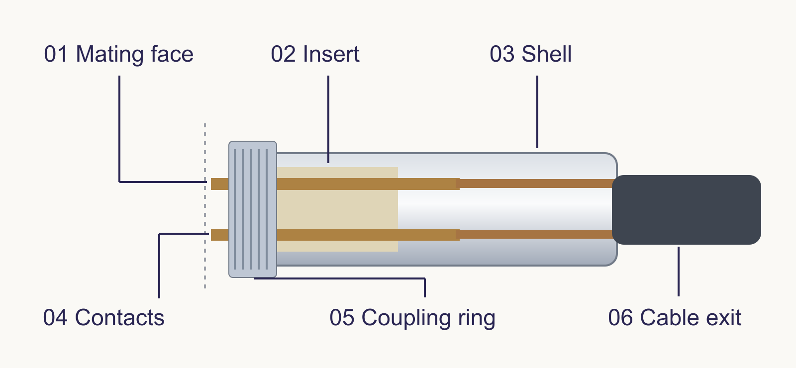
Housing is a broad name for the body that supports a connector’s parts. A shell is its outer protective structure. An insert holds contacts in their positions and electrically separates them. Depending on the design, these functions may be separate parts or combined in one molded body.
A rear accessory fitted to a connector shell. It can organize the cable exit, support a clamp, terminate a cable shield or accommodate seals. A backshell and a flexible strain-relief boot can appear together; they have different mechanical roles.
A rotating ring that secures the mating halves, commonly by a thread. It is different from a panel-mounting nut, which fixes one connector to a wall or panel. The contacts do not need to rotate with the coupling nut.
A mechanical catch that holds a connection closed until released. A latch may be part of a plastic housing, a metal clip or a separate mechanism. Its retention function is distinct from the spring pressure between electrical contacts.
A key is a projecting alignment feature; a keyway is the matching recess or channel. Their locations guide insertion and can block the wrong orientation or an incompatible variant before the contacts engage.
Seal describes a barrier against leakage or ingress. A gasket seals between joined surfaces. An O-ring is a ring with a circular cross-section that seals when compressed in its intended groove. A connector may need separate seals at its mating face, panel and cable entry.
A flexible part surrounding a wire or cable at an opening. It can cushion the wire against an edge and, in a sealing design, close the gap around it. Unused wire cavities may require separate sealing plugs.
A feature that transfers cable pulling or bending loads away from electrical terminations. Examples include a cable clamp and a flexible molded boot. Their shapes and load paths differ; a decorative sleeve is not automatically an effective strain relief.
The geometry and arrangement where two connector halves meet: contacts, guiding surfaces, keys and any interface seals. Sharing an interface name does not by itself establish the wiring or performance of a complete cable assembly.
Mounting describes where a connector is supported. Termination describes how its contacts join a wire or a circuit board.
Plug and receptacle describe the mating components according to a connector family’s naming convention. A receptacle is often fixed to equipment, while a plug is often on a cable; inline exceptions exist. Jack commonly names the receiving component in RF and other interfaces. Contact gender must be identified separately.
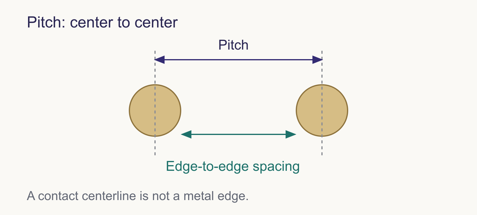
The center-to-center distance between adjacent contact positions in a stated row or pattern, usually in millimeters. Multi-row connectors can have different row and column pitches. Pitch is not the free air gap between the metal surfaces.
Scroll sideways to see the full diagram ↔
Positions count the available contact locations. Populated contacts count those actually installed. A six-position housing can therefore contain fewer than six contacts. Blank positions may serve keying, spacing or assembly needs; the drawing identifies the intended arrangement.
Polarization prevents an unintended mating orientation. Keying uses geometric features to guide or restrict mating. Coding distinguishes variants within a family, sometimes using different key locations. For example, M12 A-coding describes an interface variant; it does not name a universal wire-color scheme.
A panel-mount connector attaches to an enclosure wall. A PCB-mount connector attaches to a printed circuit board. A cable-mount connector terminates a cable. These descriptions can overlap: a panel receptacle may also have leads soldered to a PCB.
These describe the relation between the mating direction and the cable exit or board connection. A right-angle cable connector turns the cable path relative to the mating axis. For board connectors, the drawing clarifies orientation relative to the board.
A wire connection made by controlled deformation of a contact barrel around a conductor. It joins the materials mechanically and electrically without solder. Some contacts have a separate insulation support crimp; that support does not replace the conductor crimp.
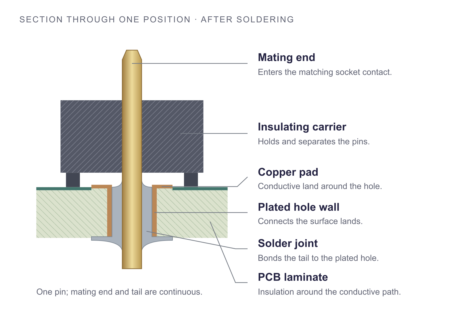
A termination made with a solder alloy that bonds the conductor to a contact or board pad. Solder cups accept wires; solder tails connect to PCB pads or holes. The contact’s mating surface is a different region from its soldered termination.
A solderless PCB connection in which a contact is pressed into a specified plated hole. A compliant section can deform to maintain pressure against the hole wall. Press-fit describes the board termination, not the way the connector’s mating halves lock together.
Surface-mount technology (SMT) joins component terminations to pads on the board surface. Through-hole leads enter holes in the board, commonly for soldering. Press-fit also uses plated holes, but forms its connection through mechanical interference rather than a solder joint.
The same metal pin forms the mating end and the board tail. The insulating carrier holds the eight pins apart.
A cable assembly combines cable with the required terminations and other parts; it may be single-ended. A wire harness groups and routes multiple wires or cables, often with branches and several endpoints. Usage overlaps, so the assembly drawing gives a clearer picture than the label alone.
Current flows through the intended conductive path. Insulation keeps that path separated from other circuits and accessible parts.
The current a specified contact or connector can carry under stated conditions. Ambient temperature, wire size, the number of loaded contacts and allowable temperature rise all matter. A per-contact value obtained with one contact loaded may differ from the value when every contact carries current.
Working voltage describes the voltage present during normal operation. A rated voltage states a manufacturer’s assigned operating value under specified conditions. AC RMS, AC peak and DC are different descriptions; a bare voltage number leaves an important part of the rating unstated.
Resistance through a mated contact connection, often reported in milliohms (mΩ). The measured result depends on where the test probes are placed and on the test method. Small contact spots and surface films affect the interface; conductor resistance can also contribute over the measured length.
Resistance between points that should be electrically isolated, such as adjacent contacts or a contact and shell. It is commonly measured with a specified DC voltage and reported in megohms (MΩ) or higher units. It measures leakage through or over insulation, rather than resistance along the intended current path.
The difference in voltage across a current-carrying part. For a resistive connection, ΔV = I × R. Increasing either current or resistance increases this drop. Resistance can change with temperature and contact condition, so a calculated example is not a substitute for an assembly rating.
Current flowing through a path intended to provide insulation. Insulating material and contamination on its surface can contribute. The test voltage, humidity and measurement arrangement affect the result. Leakage current and useful load current describe different paths.
The increase in the measured part’s temperature above the defined ambient or reference temperature. It is a temperature difference, not the final absolute temperature. Resistive heating follows P = I²R for the resistance being considered; heat removal determines the resulting temperature rise.
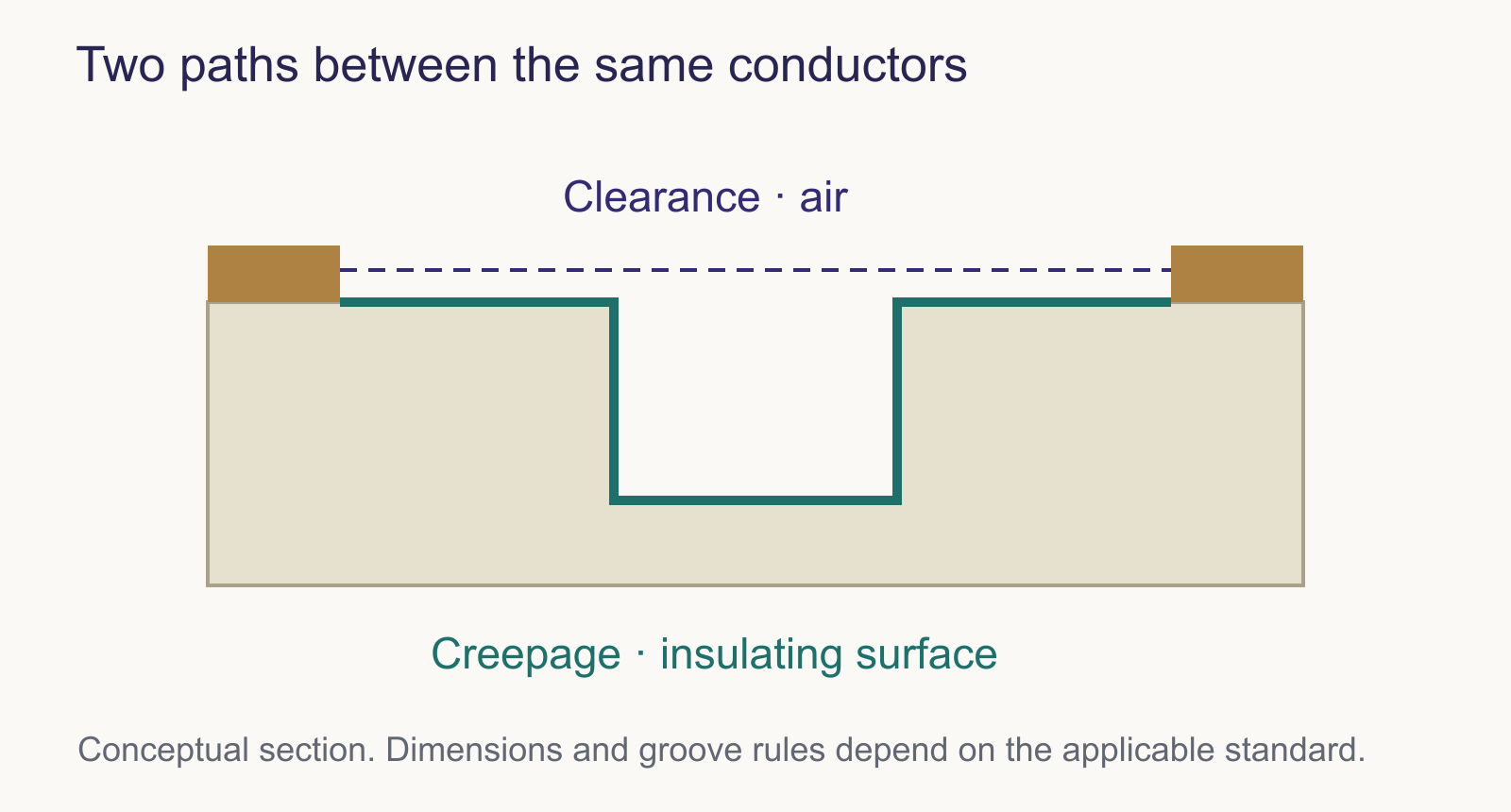
Clearance is the shortest distance through air between conductive parts. Creepage is the shortest path along a solid insulating surface between them. A groove can lengthen the surface path without increasing the direct air gap. Required distances depend on the applicable insulation rules and operating conditions.
Scroll sideways to see the full diagram ↔
Continuity means an electrical path exists between specified points. An open circuit interrupts an intended path. A short circuit creates an unintended low-resistance connection between points that should remain separate. A continuity beep alone does not establish current capacity, insulation quality or high-speed signal performance.
A connector is an electrical component with moving, loaded surfaces. Several different forces act at the same time.
The force pressing mating contact surfaces together, perpendicular to their local interface. A deflected spring contact often supplies this force. It influences the actual conducting contact spots, friction and wear; it is not the same quantity as the force used to push a whole connector together.
Scroll sideways to see the full diagram ↔
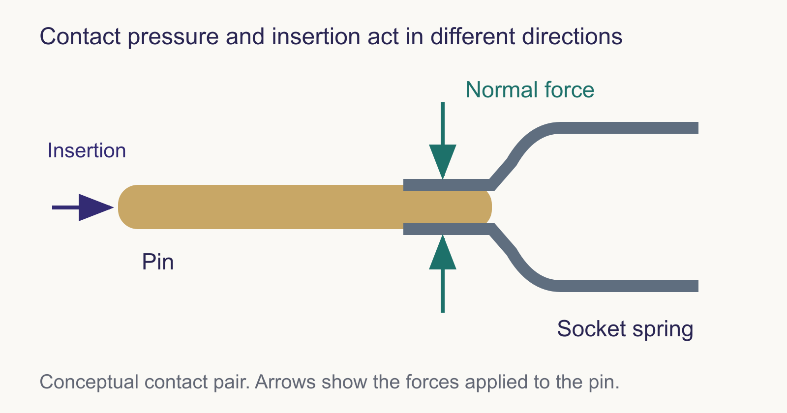
The force needed to engage or separate the mating parts, measured under a defined procedure. Contact friction, seals and guiding features can all contribute. Rotating a threaded coupling introduces a torque, usually expressed in N·m, which should not be confused with a linear force in newtons (N).
The resistance of a contact to being pushed or pulled out of its intended position in the housing. It concerns the contact-to-housing attachment. Connector latch retention and wire pull-out strength describe other joints and require different tests.
One complete mating and unmating sequence is a cycle. Durability describes how many specified cycles a connector can undergo while meeting the defined acceptance criteria. A cycle rating is not a direct prediction of service years, and it does not automatically permit connecting or disconnecting under load.
The sliding movement between contact surfaces as they engage. Wipe can help disrupt surface films and establish contact, but it also produces wear. The wiping distance is only the portion with surface contact, not necessarily the connector’s full insertion travel.
Small repeated movements at a contact interface can wear the surface and produce debris. Where oxidation of exposed material or wear debris accompanies this movement, the process is called fretting corrosion. It can raise resistance even though the connector has never been deliberately unplugged.
The permitted variation of a dimension or other specified characteristic. Parts must work together across these allowed variations. A nominal diameter alone does not describe the mating fit: the size limits, alignment and geometry also influence how the parts assemble.
A protection label describes a particular exposure or test. Dust, moisture, impact and combustion are different questions.
An enclosure protection code defined by IEC 60529. The first characteristic numeral concerns access to hazardous parts and solid foreign objects; the second concerns water ingress. For connectors, the stated protection may require the halves to be fully mated or a specified cap to be fitted.
An environmentally sealed connector limits ingress under specified conditions. Hermetic describes a gas-tight barrier evaluated against a defined leak-rate requirement, often achieved with glass-to-metal or ceramic seals. An IP water-protection rating alone does not establish hermetic performance.
The temperature range within which a component is specified to operate under its stated conditions. Current-generated heating and the temperature limits of contacts, housing, seals and cable can constrain the assembly. A brief soldering temperature or a resin’s heat-deflection temperature is a different property.
Vibration is repeated mechanical motion; shock is a transient mechanical event. Tests describe the applied motion or pulse, its severity, duration and directions. Connector acceptance may include physical condition and electrical interruptions. A passing vibration result does not imply that every shock exposure is covered.
Repeated movement between specified temperatures, with defined dwell and transition conditions. Different materials expand and contract by different amounts, loading joints and seals. A cycle test probes the effects of changing temperature; a steady high-temperature exposure probes a different condition.
A controlled exposure to a salt-containing mist used to evaluate corrosion behavior. Hours in the chamber are a test duration, not a direct conversion to years outdoors. Specimen preparation, coating condition and acceptance criteria are needed to interpret the result.
A classification of how plastic specimens behave under specified small-scale flame tests. Ratings such as HB and V-0 use different test arrangements and criteria. The classification belongs to a particular material formulation and tested thickness; V-0 does not mean noncombustible or fireproof.
The spring underneath, the surface finish and the insulating body do different jobs. Their names should not be treated as a single quality ranking.
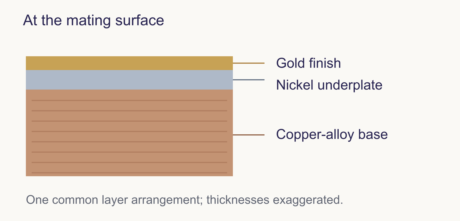
The base material supplies the bulk of a part’s structure. Plating is a deposited metallic surface layer. For a contact, the base alloy contributes conductivity and mechanical behavior, while plating changes the properties of the mating or termination surface. One contact can have different finishes in different regions.
Scroll sideways to see the full diagram ↔
These are families of copper alloys. Brass is principally copper-zinc; phosphor bronze is a copper-tin alloy with phosphorus; beryllium copper contains beryllium and is available in heat-treatable grades. Strength, conductivity and spring behavior depend on the exact composition, temper and processing. The family name alone does not give those values.
These finishes offer different contact-surface behavior. Gold resists oxidation and is widely used for signal contacts. Tin is economical but its surface oxide and fretting behavior require suitable contact design. Silver offers high conductivity and is used in many power contacts, while tarnishing behavior matters in its intended environment.
A nickel layer between the base metal and an outer finish, often gold. It can act as a diffusion barrier and support the plated surface. Its purpose differs from that of the exposed mating finish; a gold-looking contact may therefore contain more than two material layers.
The thickness of a deposited layer, commonly stated in micrometers (µm) or microinches (µin). Location matters: a contact may be selectively plated only at the mating zone. More thickness is not a complete quality specification; layer composition, porosity, hardness and the underlying finish also matter.
These identify polymer families used in engineered parts. Fillers, reinforcement and additives create grades with different properties within each family. A connector body’s material name does not by itself establish its operating temperature, flame classification or chemical resistance.
Scroll sideways to see all columns ↔
| Abbreviation | Name | What the abbreviation identifies |
|---|---|---|
| PA66 | Polyamide 66 (nylon 66) | A particular polyamide family |
| PBT | Polybutylene terephthalate | A thermoplastic polyester |
| LCP | Liquid crystal polymer | A family with ordered molecular structures |
| PPS | Polyphenylene sulfide | A high-performance thermoplastic family |
| PEEK | Polyetheretherketone | A member of the polyaryletherketone family |
The grade supplies the missing detail: reinforcement, additives and test conditions. Heat-deflection temperature measures deformation under a specified load; it is not a continuous-use temperature rating.
A thermoplastic softens with heating and can be processed again within its usable thermal limits. A thermoset forms a cross-linked structure during cure and cannot simply be remelted and reshaped. These describe material behavior, not a universal ranking of connector durability.
Stamping cuts and forms metal sheet or strip using tooling. Machining removes material from stock to create the part. Both processes can produce electrical contacts; geometry, alloy, finish and contact design determine the result, rather than the manufacturing label alone.
Injection molding forms a part by injecting moldable material into a cavity. Overmolding forms material around an existing part or assembly, such as a cable termination. A molded cable exit can provide support and protection, but a specific ingress rating depends on the complete sealing design.
At higher frequencies, a connection affects the shape and propagation of a signal as well as carrying current.
The voltage-to-current ratio of a traveling wave on a transmission line. It depends on the line’s geometry and materials and is expressed in ohms (Ω). A nominal 50 Ω coaxial interface is not a 50 Ω DC resistor inserted in series with the signal.
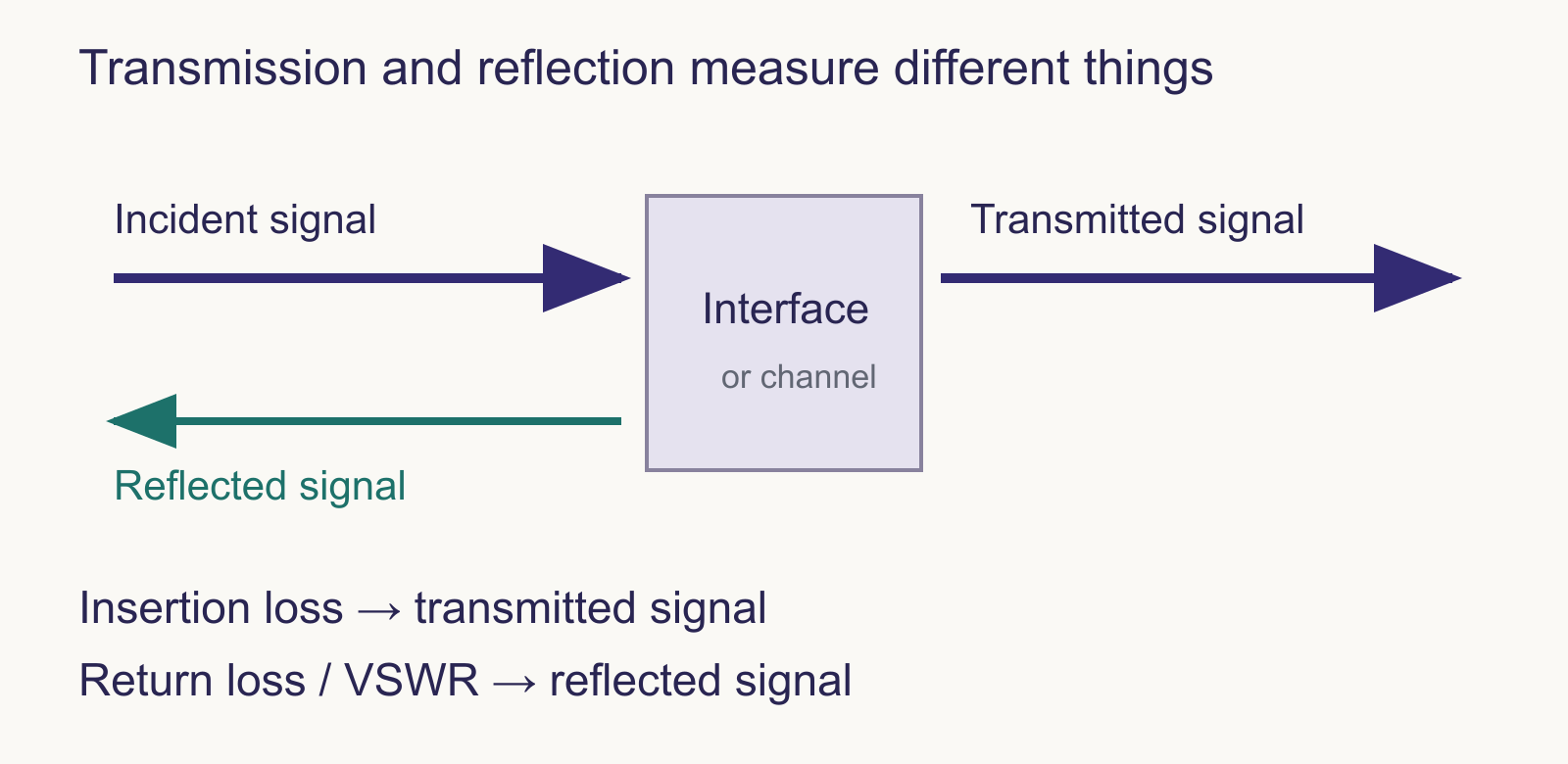
The reduction in transmitted signal caused by inserting a component or channel, stated for defined frequencies and reference conditions. As a positive loss in dB, a smaller value means less loss. A network analyzer may instead show transmission magnitude, such as S21, as a negative dB value.
A measure of how little signal is reflected back from an impedance mismatch. Using the usual positive return-loss convention, a higher dB value means less reflection. The same reflection may appear as a negative S11 magnitude on an analyzer; the sign convention changes how the number is written.
Voltage standing wave ratio: the maximum to minimum voltage magnitude of the standing-wave pattern along a transmission line. It expresses mismatch without a dB unit. The ideal matched value is 1:1; larger ratios indicate more reflection. VSWR does not separately measure dissipative transmission loss.
Scroll sideways to see the full diagram ↔
| Return loss | Reflected power | VSWR |
|---|---|---|
| 10 dB | 10% | 1.92:1 |
| 20 dB | 1% | 1.22:1 |
| 30 dB | 0.1% | 1.07:1 |
Calculated for the usual real reference impedance: |Γ| = 10−RL/20, reflected-power fraction = |Γ|², and VSWR = (1 + |Γ|)/(1 − |Γ|). Values are rounded. These conversions describe mismatch, not the insertion loss of a complete cable.
Unwanted signal coupling from one circuit or signal path into another. Near-end crosstalk (NEXT) is observed at the same end as the disturbing source; far-end crosstalk (FEXT) is observed at the opposite end. Contact arrangement, spacing, shielding and the complete channel influence it.
How much a shield reduces electromagnetic coupling under a defined test, commonly expressed in dB versus frequency. A connector shell, cable shield and their terminations form part of the shielding path. A metal enclosure or braided cable alone does not establish the effectiveness of the complete assembly.
Two conductors that carry a signal represented by the voltage difference between them. The receiver responds to that difference. Noise coupled equally into both can be rejected within the receiver’s limits; imbalance and unequal propagation can reduce that benefit. A pair still needs an appropriate electromagnetic return-path environment.
Bandwidth describes a usable frequency range or frequency span, measured in hertz. Data rate describes how many bits are carried per second. They are related through modulation, coding and channel behavior, but GHz and Gb/s are not interchangeable units. A connector’s frequency specification alone does not define a complete link’s data rate.
Manufacturer explanations, material data and standards organizations provide more detail on these concepts.
For Renhotec product drawings and catalogs, visit the download center.