60A - 120A
125A - 200A
250A - 350A
400A - 480A
Renhotec · Product Guides
Match the device interface first. Then check the electrical limits, cable and space needed to install the connection.
If you are replacing a sensor cable, the port on the sensor usually determines whether you need M8 or M12. For a new design, M8 can help where connector space is tight; M12 offers a broad choice of signal, data and power interfaces. The right choice still depends on the specific coding, contacts and assembly.
The starting point
Start with the device part number and connection diagram. Match the mating interface, including its locking system, coding, contact arrangement and male or female contacts. Then identify what is required at the other end of the cable.
An M8 sensor and an M12 I/O port may need a cable with different connectors at its two ends. That cable must carry the required signals to the correct contacts; changing connector size alone does not establish compatibility.
Work from the circuits and installation. Decide how many contacts you need, what they carry and which devices will connect. Compare assemblies that meet those requirements, including the space around the connector and the cable exit.
Choose M8 when an appropriate configuration fits the electrical task and helps meet the space constraint. Choose M12 when its available interface or assembly options suit the system better.
Swipe or scroll horizontally to compare all columns.
| Selection point | M8 | M12 |
|---|---|---|
| Screw mating interface | M8 × 1 | M12 × 1 |
| Space | Smaller nominal mating thread; compare the complete body and cable exit | Larger nominal mating thread; housing dimensions vary with the design |
| Contact configurations | 3 and 4 positions are common starting points; other arrangements also exist | Multiple contact counts and codings for different signal, data and power tasks |
| Electrical and environmental limits | Read the selected configuration’s ratings and conditions. Neither family name gives a universal current, voltage or IP rating. | |
| Direct interchangeability | M8 and M12 mating interfaces do not plug directly into one another. An adapter or mixed-end cable also needs the correct electrical mapping. | |
Renhotec catalog: M8 screw-locking connectors · M12 screw-locking connectors.
Identify the interface
Check the mating end and the cable end separately. The mating end must fit the device port; the rear gland must fit the cable. The coding and contact arrangement come from the connector drawing, and the signal assignment comes from the device diagram.
Know which part to check
Coding is the mechanical keying that aligns the mating inserts and helps prevent incorrect mating. A-coded and D-coded four-position M12 connectors have different interfaces. Male and female describe the pin and socket contacts; a threaded metal shell alone is not enough to identify them. M12-A interface reference.
A-coding is widely used for sensor and actuator connections. If the equipment specifies a data or power interface, follow that specification rather than selecting a similar-looking A-coded connector. Also avoid the shortcut “M8 is only for sensors”: D-coded M8 products for Ethernet exist. This does not make an ordinary M8 A-coded sensor cable an Ethernet cable.
For an A-coded M12 sensor connection, use the 4-pin and 5-pin pinout reference alongside the device diagram. Check the viewing direction when comparing contact numbers. A wire-color convention cannot replace the device’s signal assignment.
Read the actual configuration
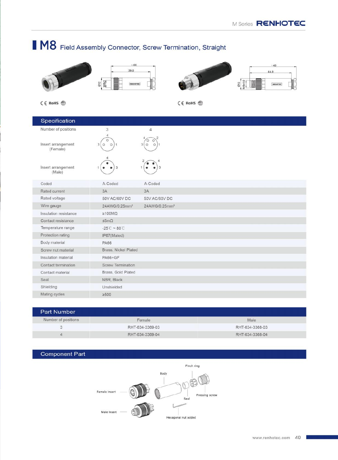
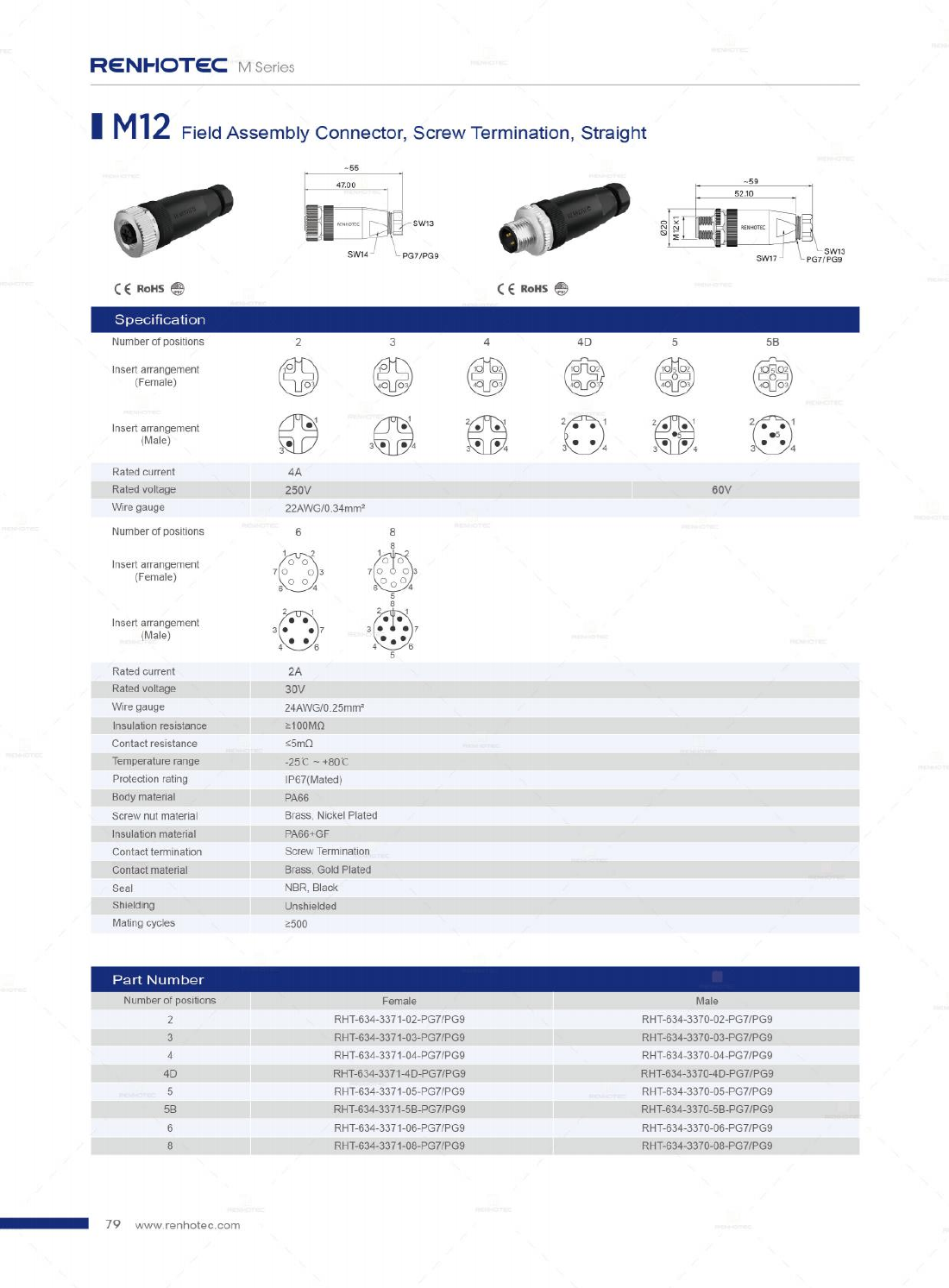
Compare the exact ordering codes. These two straight, four-position A-coded male plugs use screw terminals, but their current and voltage ratings differ.
Swipe or scroll horizontally to compare all columns.
| Catalog field | M8 · RHT-634-3368-04 | M12 · RHT-634-3370-04-PG7 |
|---|---|---|
| Contacts / termination | Male, A-coded / screw | Male, A-coded / screw |
| Rated current | 3 A | 4 A |
| Rated voltage | 50 V AC / 60 V DC | 250 V; AC/DC not specified in the catalog entry |
| Protection rating | IP67 (mated) | IP67 (mated) |
| Temperature range | −25°C to +80°C | −25°C to +80°C |
| Source and product | Catalog p. 40 View M8 product | Catalog p. 79 View M12 product |
For the M12 entry, obtain the applicable AC or DC rating for your circuit. The temperature range also does not establish that the full rated current is available at every temperature with every contact loaded. Include ambient temperature, simultaneous loading and conductor details when checking the assembly’s suitability.
Check the whole installation
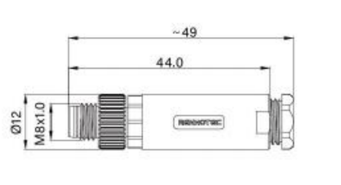
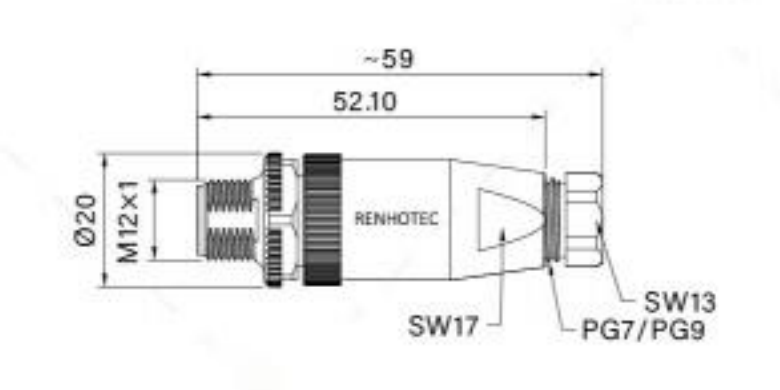
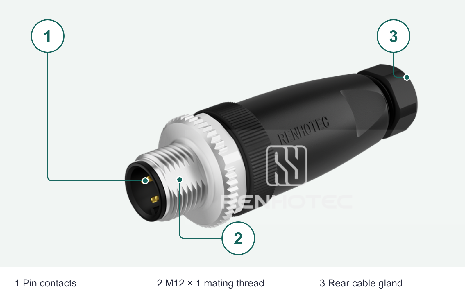
For screw-locking interfaces, M8 and M12 identify nominal metric thread sizes. The housing around that thread is larger, and the complete plug extends behind it. Check the housing and installation dimensions before placing adjacent ports or routing the cable.
Thread · body · length
Two straight male field-wireable plugs from the Renhotec catalog.
Leave additional room for the mating part, access to tighten the connection, and the cable’s permitted bend radius.
A straight connector needs room behind the port for its body and cable to leave without a sharp bend. A right-angle connector can redirect that exit, but its orientation and side clearance must suit the actual port position. On a row of closely spaced ports, check whether a hand or the specified tool can still reach the locking nut after adjacent cables are installed.
For a panel-mount receptacle, use its mounting drawing for the cut-out, panel thickness and seal arrangement. The mating thread and panel-fixing thread can be different. Check the connection behind the panel as well: wires, solder cups and PCB tails require different space and assembly access.
Choose the assembly
A molded cable assembly gives you a factory-terminated connector and cable. Specify the required length, the connector at each end or flying leads, and the cable construction. It is a useful starting point when the route and endpoints are known.
RHT-M8002-03 is a straight, three-position A-coded M8 female, single-ended assembly. Its device end and open cable end suit a different installation task from the field-wireable male plugs compared above.

Renhotec’s M8 range and M12 range include different construction options. Select the form before comparing complete ordering codes.
Fixed wiring inside a cabinet and a cable that bends on every machine cycle are different applications. Specify the movement, bend radius, expected cycles and exposure to oils or cleaning agents. PVC or PUR identifies a jacket material; it does not, by itself, establish a drag-chain rating or resistance to a particular chemical.
Where the device or network calls for shielding, select the cable and connectors as one shielded path and follow the equipment’s termination instructions. Do not assume a metal-looking connector housing establishes the required shield connection.
Define the operating state
Both four-position examples above say IP67 (mated). That condition matters whenever a sensor is unplugged for service. The rating does not establish protection for an exposed, disconnected port.
Use the specified mating pair and complete the sealing and locking steps in the assembly instructions. For a field connector, cable fit at the rear gland is part of the installation.
Check whether the open port needs a rated protective cap or another documented protective arrangement. Do not assume the connected-state rating continues after unplugging.
Specify wash conditions, chemicals, vibration and cable movement separately. An IP entry alone does not answer these questions or prove that all materials suit the environment.
Compare the actual connector and cable temperature limits with their location on the machine. An assembly beside a hot actuator may experience different conditions from the ambient air quoted for the control cabinet.
Apply the checks
Start with the requirement that determines the choice in each of these examples.
Known: the sensor drawing specifies a screw-locking, three-position A-coded M8 male interface.
Decision: look for the corresponding female cable end, then match the signal assignment and the controller-side connection. A suitably specified single-ended cordset may fit a terminal-wired controller. A four-position M12 cable is not a direct replacement.
Known: the equipment manual requires a particular D-coded interface and network cable.
Decision: match the named connector size and coding, then the network cable specification. A four-contact A-coded sensor lead is not interchangeable simply because it has four contacts. Use the device’s specified M8-D or M12-D interface.
Known: the circuits need eight contacts and include a 3 A load.
Decision: the eight-position M12 screw-termination group shown on catalog p. 79 is listed at 2 A, so that entry does not meet the 3 A requirement. Consider a different documented configuration or a revised circuit/interface arrangement. The four-position version’s 4 A rating cannot be reused.