60A - 120A
125A - 200A
250A - 350A
400A - 480A
On this page
Applications & Technology
A shield helps control electrical interference. Its material, position and termination determine how well it can do that job.
A cable shield is a conductive layer around insulated conductors or groups of conductors. It helps reduce electromagnetic interference (EMI) reaching the signal wires and can limit interference emitted by the cable. A screened cable is another name for a shielded cable.
Consider a sensor lead routed near a switching motor drive. The drive and its power wiring can couple unwanted energy into the signal circuit. A shield acts on that coupling path; routing, the signal circuit and the way the shield connects to the equipment also matter. Kollmorgen’s servo-cable guidance describes these incoming and outgoing interference paths.
The outer plastic jacket protects the cable from its surroundings. The shield serves a different electrical purpose. Neither the word shielded nor a metal-looking sleeve establishes an IP rating, a permitted current or an EMC result for a finished machine.
Start with the equipment’s cable requirement. An unshielded cable can be appropriate for a system designed around it; replacing the specified shielded cable with one of the same conductor size can remove part of the intended interference control.
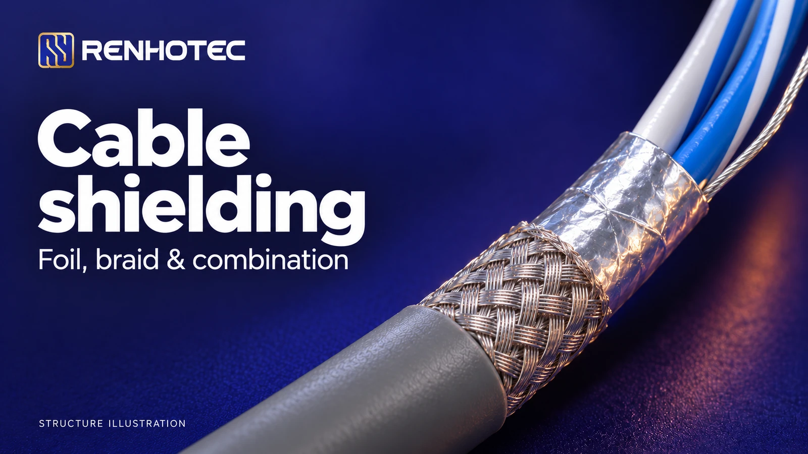
“Foil” and “braid” describe how the conductive layer is made. They do not tell you whether it surrounds the whole cable or each signal pair.
A thin metallic layer, commonly aluminium on a supporting film, wraps around the cores. An overlapping wrap can provide full geometric coverage with little added bulk.
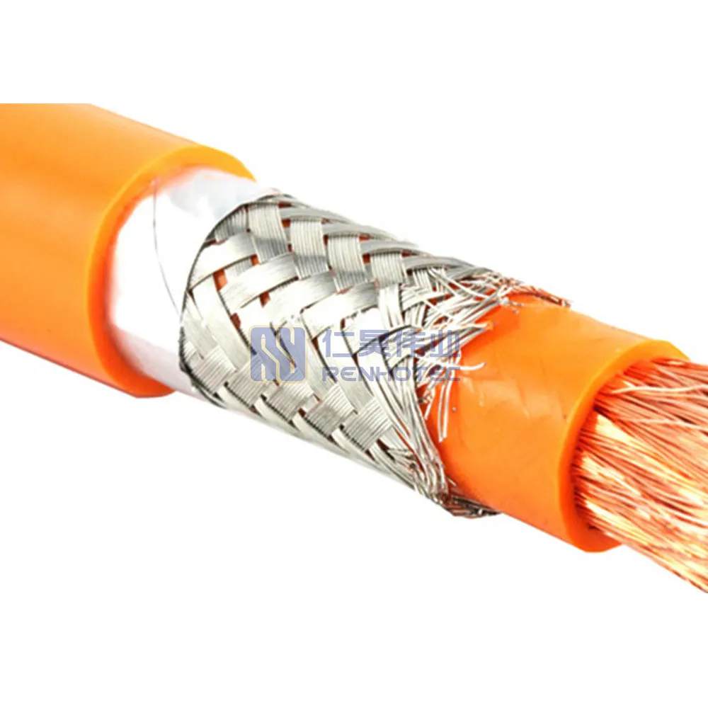
Interwoven wires, commonly bare or tinned copper, form a conductive sleeve. The weave leaves openings; its coverage depends on the braid construction.
The foil covers gaps beneath the braid. The braid adds a conductive path and can provide a practical termination surface. The finished design determines the result.
Material illustrations are schematic. See Multi/Cable’s foil and braid construction notes.
A drain wire maintains electrical contact with the conductive face of a foil shield and provides a connection point. It does not surround the cores and cannot replace the shielding layer.
Layer order matters. Alpha Wire M8704020 specifies aluminium/Mylar tape with a minimum 25% overlap, foil facing inward and a 16 AWG tinned-copper drain wire. Its separate clear Mylar core wrap is a different layer. A shiny tape or a film wrap should not automatically be identified as the shield.
Use the construction to narrow the options, then compare cables intended for the same electrical and mechanical duty.
| Construction | Reason to consider it | Check before specifying it |
|---|---|---|
| Foil | Broad surface coverage in a thin layer, including around individual pairs. | Overlap, conductive-face orientation and the intended drain-wire or shield contact. |
| Braid | A woven metal sleeve where the design needs a robust shield connection. | Braid material, coverage and the complete cable’s bending or torsion rating. |
| Foil + braid | Two complementary shield elements in one construction. | How each layer reaches the termination, plus finished diameter and application-specific EMC evidence. |
Construction principles: Kollmorgen, “Three Types of Shields”. The questions above apply to the complete cable assembly.
100% coveragedoes not mean100% noise rejection
Coverage describes how much of the underlying surface is covered by the shield. It is not a dB value and says nothing by itself about the connector transition.
For example, Alpha Wire 3469C lists aluminium/Mylar tape with at least 25% overlap and a tinned-copper braid with at least 65% coverage. That 65% describes the braid alone. It does not mean that 35% of the complete foil-and-braid shield is uncovered.
A 95% braid cannot be ranked against that construction from the percentages alone. Compare the relevant frequency range and a defined test result. IEC 62153-4-3:2013+AMD1:2024, for example, specifies a triaxial method for surface transfer impedance; its scope states that the method measures only the magnetic component of transfer impedance. A test method and its scope convey information that a coverage figure does not.
Foil construction alone is not a reason to reject a cable for movement. Belden 50105FS-R combines aluminium/Mylar foil with a tinned-tinsel-wire braid and is specified for continuous-flex applications. That is a rating for a particular cable, not permission to flex every foil-shielded design.
A bend radius for fixed installation also does not establish a drag-chain or torsion rating. For a moving axis, match the stated type of motion, bend radius and operating conditions before comparing shield materials.
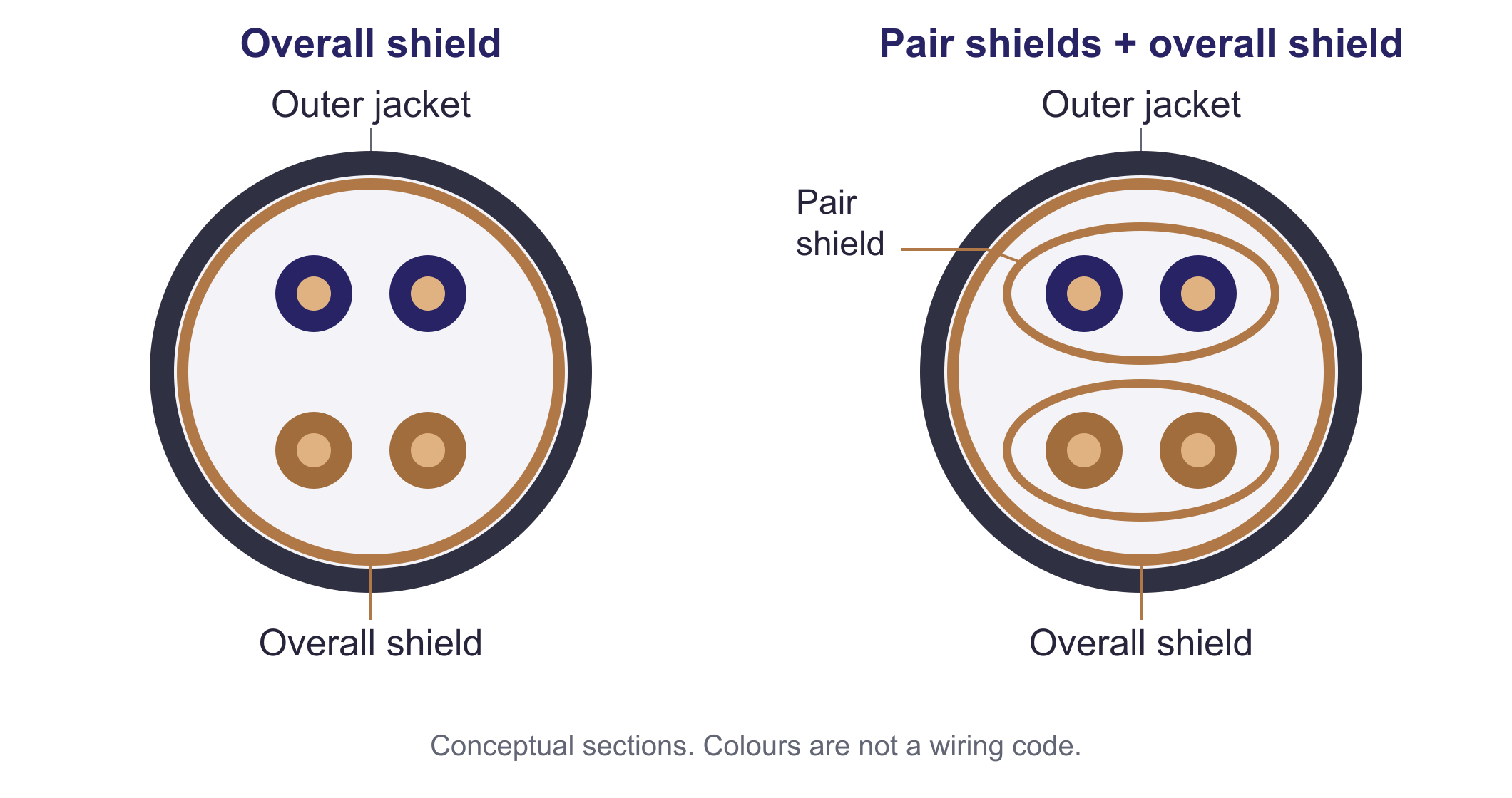
An overall shield encloses the bundle. Individual pair shields put a conductive boundary around each pair, helping reduce coupling between circuits within the same cable. A cable can use both. Multi/Cable’s shielding notes distinguish these arrangements.
One common boundary surrounds the bundle.
Each pair also has its own boundary.
Twisting is a separate part of the design. In balanced data links, the pair geometry and differential transmission help reject interference; adding an overall shield does not replace them. Beckhoff’s Ethernet cabling guidance explains their different roles.
A real braid example is LAPP UNITRONIC LiYCY (TP), part 0035830: a 2 × 2 × 1.0 mm² cable with twisted pairs and an overall tinned-copper braid. “Twisted pair” here does not mean that every pair has an individual shield.
The shield must meet the connector, cable gland or equipment enclosure through the contact arrangement specified for the system. A long exposed section or a poor transition can undermine an otherwise suitable cable.
A short, circumferential contact limits the interruption at the enclosure.
The narrow lead adds inductance and becomes less effective as frequency rises.
Beckhoff’s analog guidance recommends a low-impedance shield connection and explains why short, broad contact is preferable to a long lead for high-frequency interference. For the arrangement described there, the drain wire alone is insufficient: the shield and drain must connect together at the designated shield point. Other circuits may specify a drain-wire termination; follow their own instructions. Do not substitute one arrangement for another solely because both provide DC continuity.
There is no universal answer for every signal and installation. Beckhoff’s EtherCAT/Ethernet guidance calls for broad, low-impedance shield connections at both ends in that context. It also discusses equalising currents where earth potentials differ. Other circuit designs can specify a different connection strategy.
Follow the device and system EMC instructions, including their bonding provisions. Protective earth, signal reference and a functional shield connection have different jobs. A shield or drain wire is not automatically a protective-earth conductor; Beckhoff’s analog equipment guidance separates these functions.
For a shielded cable assembly, the useful description connects the cable construction to the finished ends. Ask for the following details together:
Renhotec RHT-M12006-04-C-XXX is listed as an M12 A-coded, four-position female straight, single-ended shielded cable assembly with a PVC jacket.
Those fields identify an assembly option. They do not specify foil versus braid, a coverage percentage or an internal shield joint. For a defined EMI requirement, request the cable construction and shield-termination drawing for the selected configuration.
Use the M12 coding guide to check the interface family, and the connector terminology glossary for other specification terms. Coding and shielding answer different selection questions.