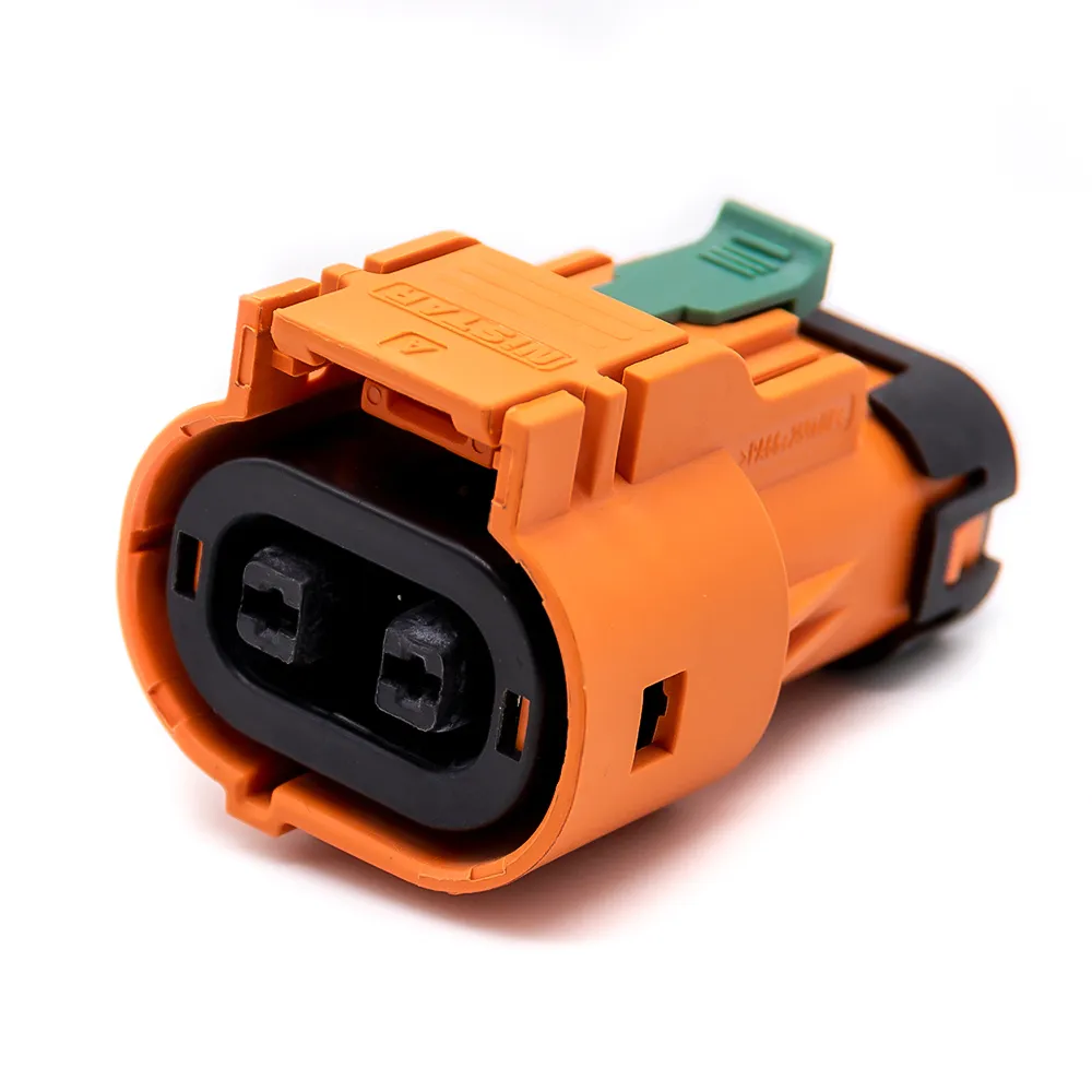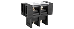
60A - 120A
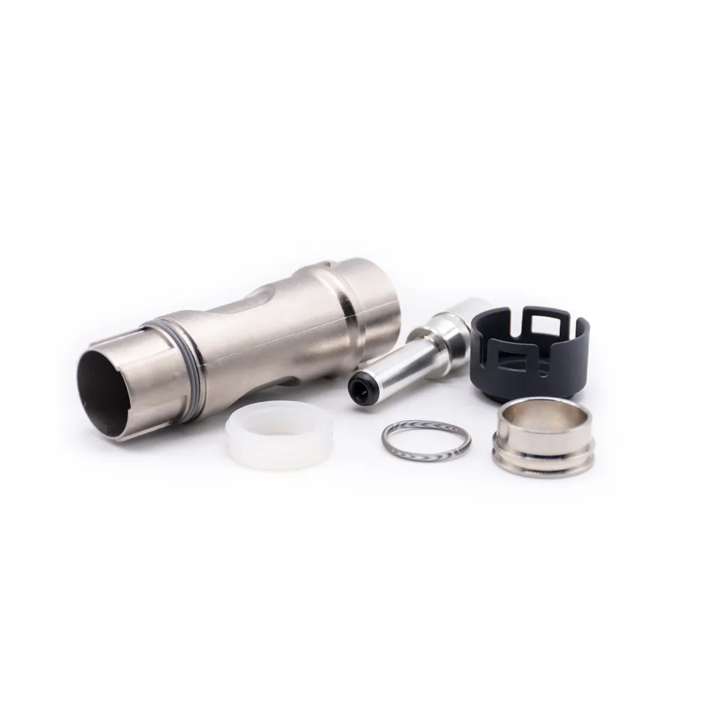
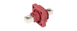
125A - 200A
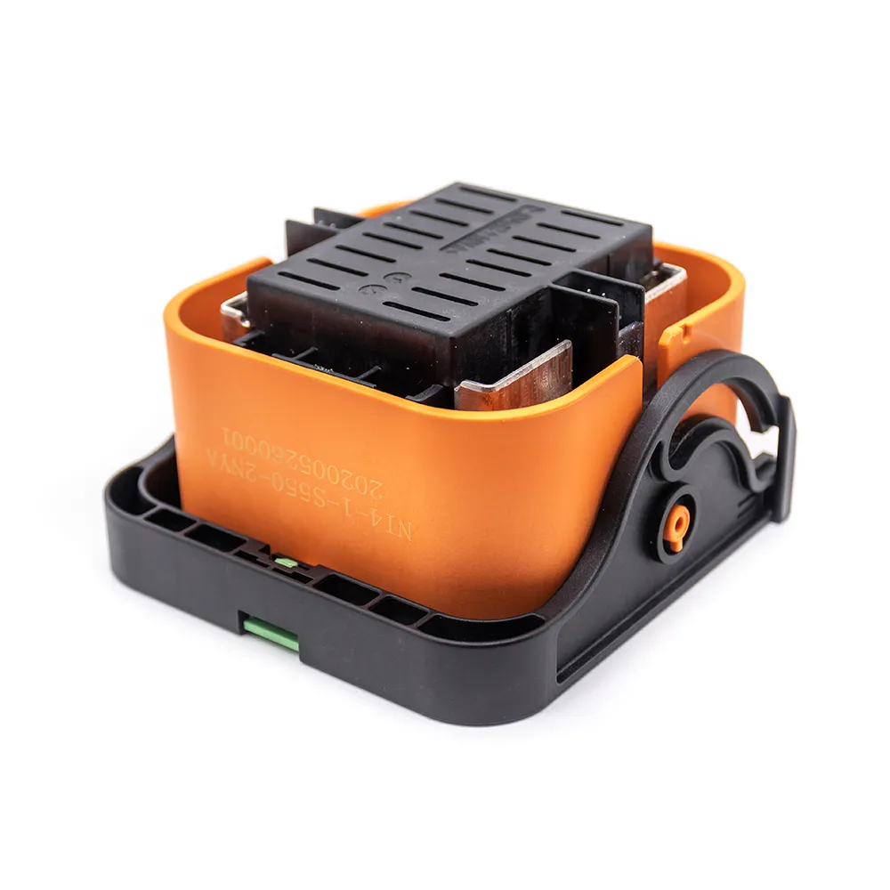
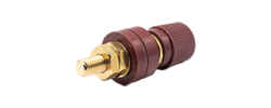
250A - 350A
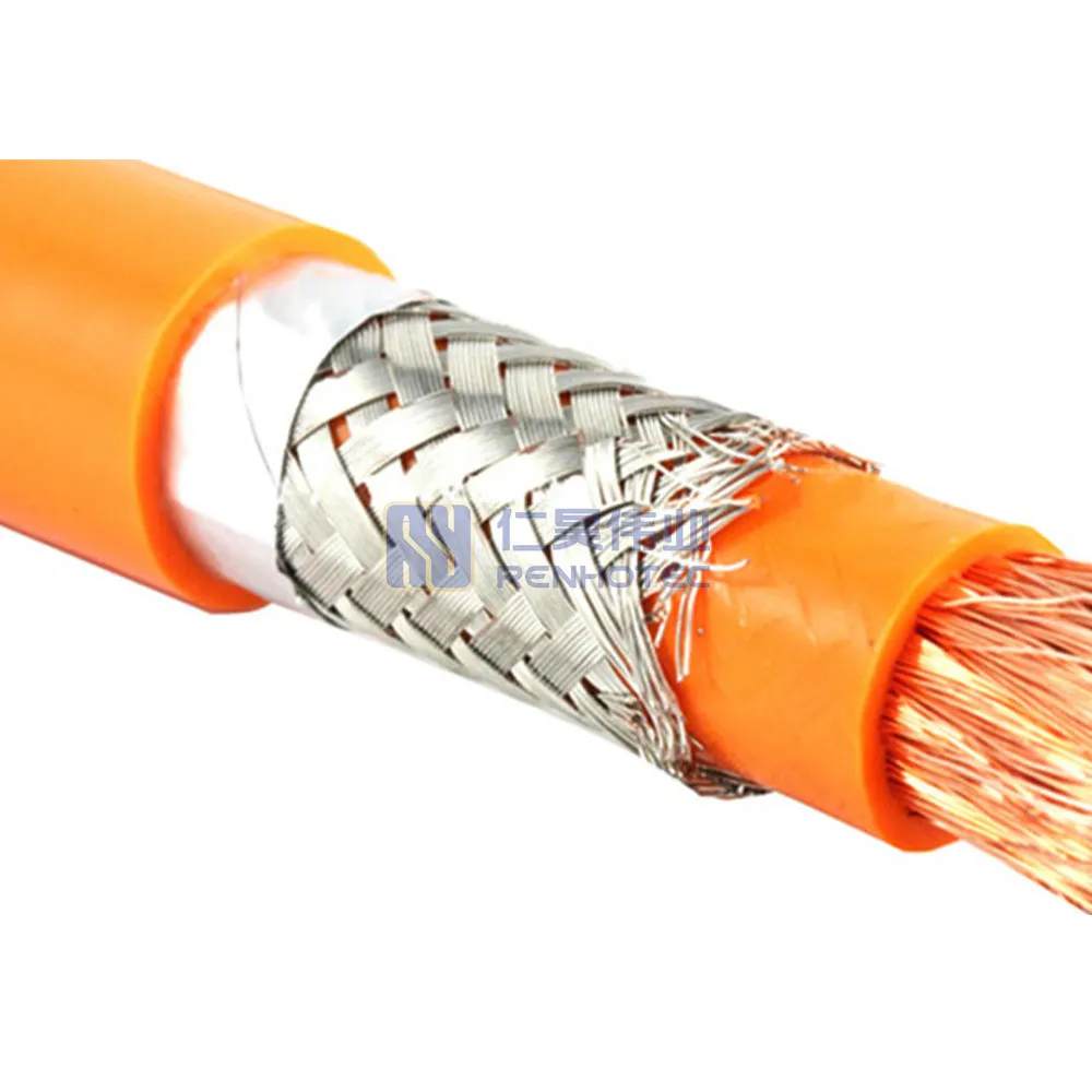
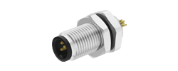
400A - 480A
On this page
Engineering guide
A copper wire's ampacity—the maximum current it can carry continuously without exceeding its insulation temperature limit—depends on the governing reference standard, the conductor temperature rating allowed by the insulation, surrounding ambient temperature, the installation's heat-dissipation path, and the number of qualifying current-carrying conductors. Use Table 1 below for baseline copper ratings from 14 AWG to 4/0 AWG, then follow the manufacturer examples to adjust for free-air routing, equipment terminal markings, multi-core and high-ambient derating, and IEC metric (mm²) installation methods.
For the North American installation conditions identified below, NFPA 70: NEC-2023 Table 310.16 provides the baseline chart. Equipment-internal wiring may use a different governing standard or manufacturer reference. The HELUKABEL Allowable Ampacity Tables reproduce the copper values below.
| AWG | 60°C Amps |
75°C Amps |
90°C Amps |
|---|---|---|---|
| 14 AWG* | 15 | 20 | 25 |
| 12 AWG* | 20 | 25 | 30 |
| 10 AWG* | 30 | 35 | 40 |
| 8 AWG | 40 | 50 | 55 |
| 6 AWG | 55 | 65 | 75 |
| 4 AWG | 70 | 85 | 95 |
| 3 AWG | 85 | 100 | 115 |
| 2 AWG | 95 | 115 | 130 |
| 1 AWG | 110 | 130 | 145 |
| 1/0 AWG | 125 | 150 | 170 |
| 2/0 AWG | 145 | 175 | 195 |
| 3/0 AWG | 165 | 200 | 225 |
| 4/0 AWG | 195 | 230 | 260 |
*Small-conductor overcurrent rule (NEC 240.4(D)): Unless specific code exceptions apply, general overcurrent protection for 14 AWG, 12 AWG, and 10 AWG copper conductors is capped at 15 A, 20 A, and 30 A, respectively. The 90°C column values for those gauges (25 A, 30 A, and 40 A) serve as starting values for ambient or conductor-count derating, not as standard breaker ratings.
When reading Table 1 for circuit design, keep five values distinct:
Some tray and power cable datasheets explicitly base their current ratings on Table 310.16. For example, Southwire Stock 443390 / SPEC 45251 specifies a 600 V Type TC-ER copper cable containing three 8 AWG THHN/THWN-2 current-carrying conductors and one 10 AWG green-insulated ground wire inside a PVC jacket.
Table 2 of the Southwire datasheet lists allowable ampacities of 50 A at 75°C and 55 A at 90°C—an exact match to the 8 AWG row of Table 1 above. The datasheet footnote specifies that those ratings are based on 2023 NEC Table 310.16 and remain subject to NEC 310.15 (ambient and bundling adjustments) and NEC 110.14(C) (equipment termination temperature limits).
This guide covers thermal current capacity by gauge; for cross-sectional area conversions (mm²), stranding geometry, and bare-conductor versus insulated outer-diameter distinctions, see our AWG to mm² Wire Size Chart.
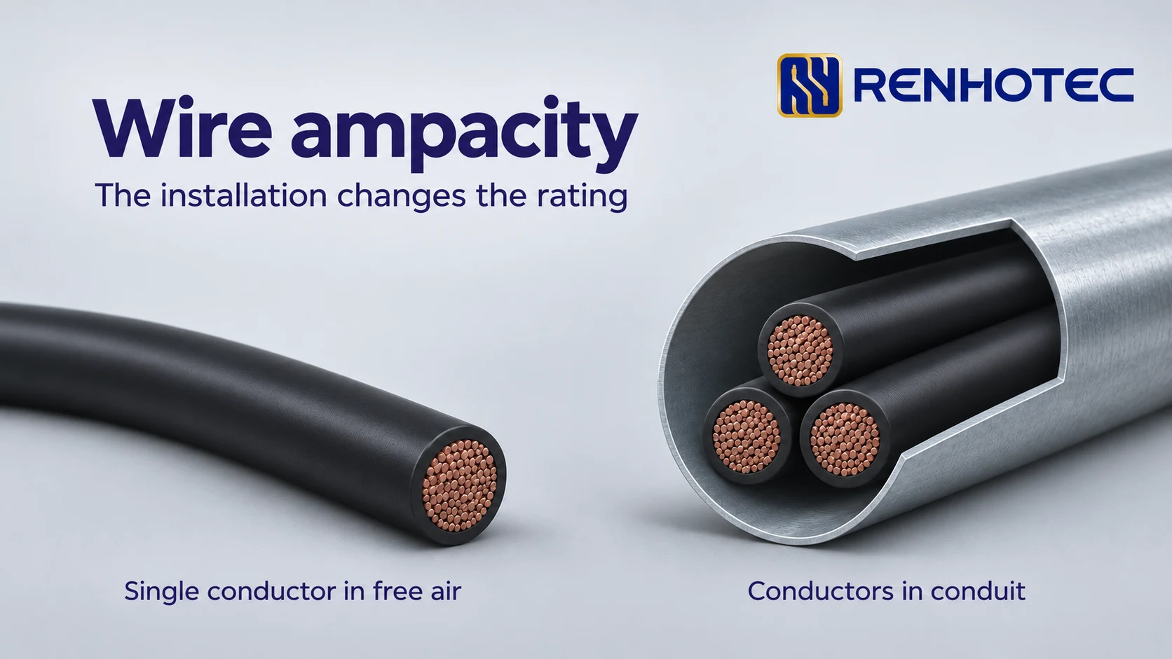
Different charts can assign different currents to the same copper gauge because their installation and temperature assumptions differ. The examples below hold gauge and temperature constant to isolate the effect of the installation.
Current flowing through a conductor segment of resistance generates total heat power . With resistance per unit length in Ω/m and current in amperes, the heat generated per unit length is measured in W/m:
For a given resistance per unit length , doubling the current quadruples the heat generated along each meter of wire. The thermal ampacity limit is the highest steady current for which heat dissipation balances this heating without exceeding the permitted conductor temperature. Changing the physical surroundings changes that heat-transfer rate.
Side-by-side tables in the HELUKABEL NEC-2023 Ampacity Reference show why an 8 AWG copper conductor rated at 90°C has two different baseline ratings at a 30°C ambient temperature:
Routing a multiconductor tray cable through open air or along an open ladder tray does not qualify its internal cores for the 80 A free-air table. Even when the outer cable sheath is exposed to air, the insulated conductors inside the jacket remain grouped together and thermally coupled, so they cannot be sized using single-conductor free-air ratings or treated as one combined conductor.
Internal equipment and electronic hook-up wire charts split ratings along similar thermal boundaries. In Remington Industries' Copper Hook-Up Wire Ampacity Charts (30°C ambient temperature), the 105°C conductor temperature column gives two reference values for 22 AWG copper:
Using the 105°C column starts with verifying the specific wire part number on its product datasheet. In Remington's UL 1007 Hook-Up Wire Data Sheet, part number 22UL1007STR specifies a 22 AWG (7/30 stranded) tinned copper conductor with 300 V PVC insulation, and the manufacturer datasheet lists UL Styles 1007 and 1569 with a 105°C temperature rating. Use the rating stated for the exact product; the generic UL 1007 label alone does not establish a 105°C continuous rating.
These two values are reference currents for the stated routing arrangements. When designing a complete wire harness, engineers must still evaluate the actual thermal conditions of the assembly—including heat buildup in larger multi-wire bundles, elevated ambient air inside enclosures, and connector pin current limits—rather than treating general hook-up chart values as certified harness ratings or mixing them with NEC building-wire derating factors.
Choosing between the 60°C, 75°C, and 90°C columns requires distinguishing the wire's continuous insulation rating from overload temperatures and then applying the temperature limits of the equipment terminals at each end.
The column headers 60°C, 75°C, and 90°C in Table 1 state the maximum continuous operating temperature allowed for the conductor for a given insulation system—not the surrounding room or enclosure air temperature (which starts at a 30°C baseline in Table 310.16).
Power cable datasheets also list short-term fault and overload limits that must not be confused with continuous table columns. On page 1 of the Southwire SPEC 45251 datasheet for 8 AWG Type TC-ER cable, three temperatures appear:
Ampacity lookup for continuous service always uses the conductor's continuous temperature rating (90°C here) and the applicable column in Table 1—never the 105°C emergency overload or 150°C short-circuit limits.
A conductor and the equipment it connects to exchange heat at their terminations. As explained in Schneider Electric FAQ FA175147 and Schneider's technical guide Wire Temperature Ratings and Terminations, a 90°C-insulated conductor may be connected to lower-rated equipment terminals, but the usable table ampacity is governed by the temperature markings of the equipment terminations at both ends of the circuit—not simply by the standalone mechanical lug rating.
Applying this rule to the 90°C-rated 8 AWG copper conductors in Southwire SPEC 45251 (50 A in the 75°C column; 55 A in the 90°C column) follows a three-step check:
50 A) instead of the 90°C column (55 A).55 A), then compare the derated result against the 75°C terminal column ceiling (50 A). The lower of the two values sets the conductor's allowable current.50 A figure is the conductor's terminal-limited column ceiling under 75°C terminations, which is then compared alongside derating results, continuous or intermittent circuit load rules, and overcurrent protection requirements.When a raceway or multiconductor cable contains more than three qualifying current-carrying conductors, or when the ambient temperature exceeds 30°C (86°F), the baseline ampacity from Table 1 is multiplied by adjustment and correction factors from the same standard system.
Before picking a conductor-count factor, determine how many cores count as current-carrying conductors (CCC) under the governing reference rules:
Page 2 of the HELUKABEL Allowable Ampacity Tables lists the NEC-2023 adjustment factors for conductor count and ambient temperature and walks through a complete calculation for HELUKABEL Part Number 710466 (TRAYCONTROL 600, 7C AWG 8), a 7-conductor 8 AWG copper tray cable rated for 90°C conductor temperature.
| Adjustment Parameter | Condition | Multiplier Factor |
|---|---|---|
| Number of Current-Carrying Conductors | 4 to 6 conductors in raceway or cable | 0.80 |
| Number of Current-Carrying Conductors | 7 to 9 conductors in raceway or cable | 0.70 |
| Ambient Temperature (90°C Conductor Column) | 36°C to 40°C (97°F to 104°F) surrounding air | 0.91 |
The derating calculation proceeds in four steps:
4–6 conductors factor of 0.80 (rather than the 7–9 conductors factor of 0.70).36–40°C bracket) gives a correction factor of 0.91:
HELUKABEL displays this result as 40 A for PN 710466 at 40°C ambient. Notice how the two temperatures and terminal rules interact: 90°C is the conductor rating used to select both the 55 A starting column and the 0.91 factor at 40°C ambient air. If this cable terminates on equipment marked for 75°C at both ends (where the 8 AWG 75°C column ceiling is 50 A), the derated value of 40.04 A (displayed as 40 A by the manufacturer) is below the 50 A terminal ceiling, so the derated ampacity governs the conductor limit.
For installations designed to IEC 60364-5-52, use the matching metric cable table. Converting an AWG size to mm² does not transfer its NEC ampacity into the IEC table. Both NEC and IEC require identifying the installation environment before reading a current value, but their reference tables organize those environments differently.
In the IEC workflow documented in Schneider Electric's Electrical Installation Guide — General method for cable sizing (sections G10 and G20, citing IEC 60364-5-52 Table B.52.4), you first classify the mounting configuration into a reference installation method (A2, B2, or C) and then read the current column for the conductor material, insulation rating, and loaded core count.
Holding all cable and ambient parameters constant—a multicore 2.5 mm² copper cable with 70°C PVC insulation, three loaded conductors, and a 30°C air ambient—Table B.52.4 gives three distinct ratings across installation methods A2, B2, and C:
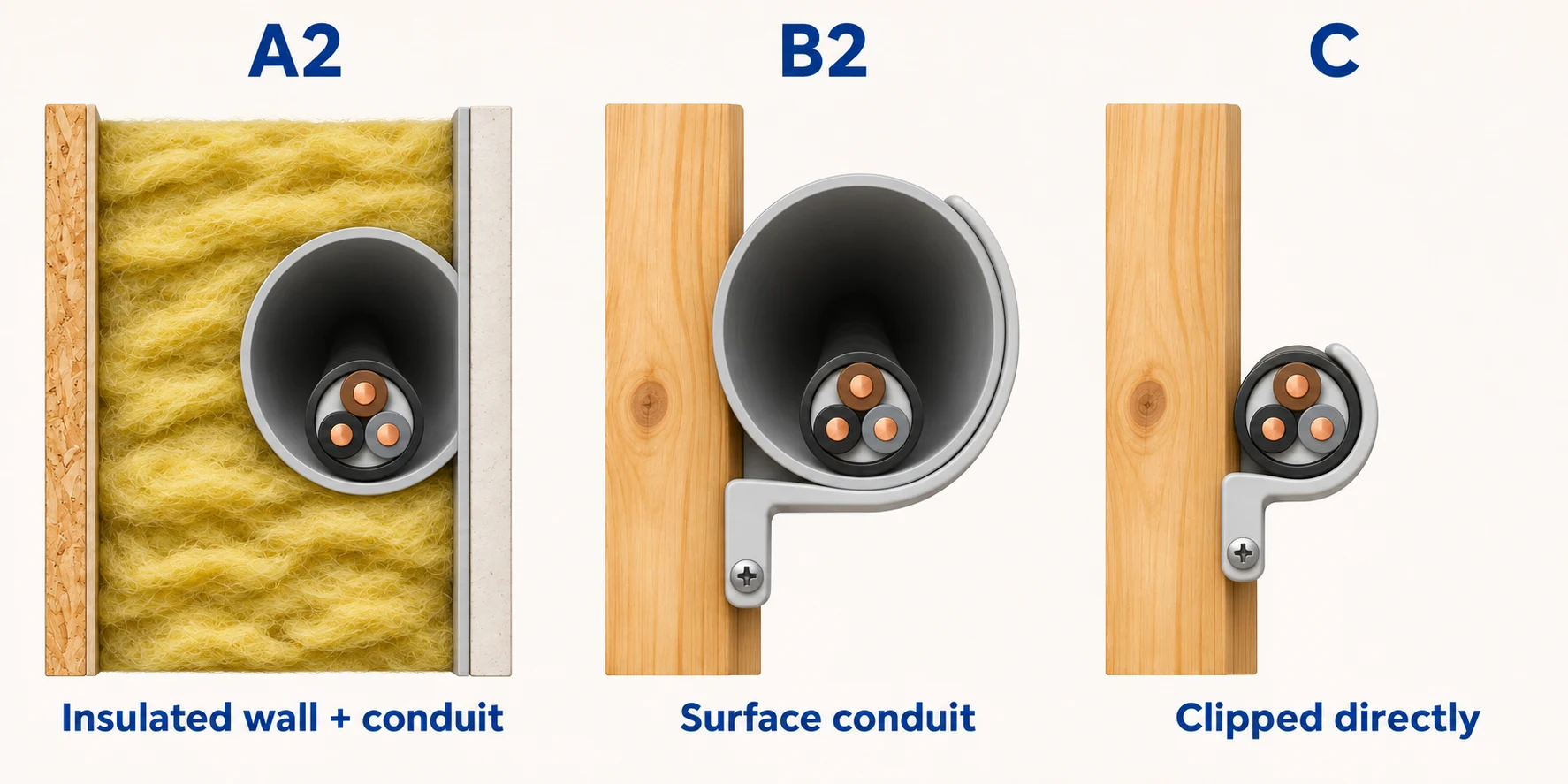
17.5 A)Running the cable inside a conduit embedded within a thermally insulated wall restricts heat transfer through both the conduit air space and the wall insulation, which leaves less capacity to remove conductor heat.20 A)Mounting the conduit on the surface of a wooden wall exposes the conduit exterior to room air while the conduit wall still encloses the cable, improving heat transfer compared with the insulated wall.24 A)Attaching the multicore cable directly to the wooden wall without a conduit allows heat to dissipate directly from the cable jacket into the wall surface and room air, removing the additional enclosure around the cable.Illustrated cross-sections based on Schneider Electric’s G10 installation methods; current values from G20. The three views use the same cable construction.
The installation method is therefore part of the rating: the 24 A value in this comparison belongs to Method C. A two-loaded-conductor table or a 90°C XLPE table describes different thermal conditions and requires a separate lookup.
A table or derated ampacity establishes the thermal limit of the conductor, while complete wire selection also accounts for voltage drop over distance and circuit-level coordination.
Ampacity and voltage drop address two separate physical constraints:
There is no universal ampacity derating percentage based only on cable run length. A short jumper with negligible voltage drop can still overheat if current exceeds its thermal limit, and a long feeder running well below its thermal ampacity can still cause a load malfunction due to excessive voltage loss. Check thermal ampacity first, then calculate voltage drop over the run length using Cable Voltage Drop Formula & Examples.
Before finalizing a wire gauge or harness specification, record the following engineering inputs and match each to its role in selection: