60A - 120A
125A - 200A
250A - 350A
400A - 480A
On this page
Connection technology
The names describe common ways to build and organize connections. The drawing tells you what you will actually receive.
A cable assembly combines cable or wires with the required terminations and associated parts. It may have connectors at both ends, or a connector at one end and prepared leads at the other. A wire harness organizes multiple wires or cables into a defined arrangement for installation, often with branches, several endpoints and attachment points.
These are useful descriptions, but suppliers do not use the terms identically. Wiring harness and cable harness are related names you may encounter. Treat the name as a starting point, then check the construction and connection requirements.
In particular, an overall jacket is not a universal dividing line. Molex offers “discrete wire cable assemblies” with straight or branched layouts and options including ties, heat-shrink tubing, woven sleeves and corrugated tubes. A cable assembly can therefore look much like something another supplier calls a harness.
Construction reference: Molex Custom Discrete Wire Cable Assemblies.
Start with three separate layers of description: the electrical paths, the way those paths are grouped, and the parts that hold and protect them. These layers explain more than the name printed at the top of a quotation.
In a typical jacketed cable assembly, the cable manufacturer has already established the conductor arrangement inside the jacket. At each end, the termination connects the conductors to the interface. A molded transition or separate strain-relief arrangement can limit the load transferred from the cable to those terminations.
The cable construction constrains the choices available at the ends. Its outside diameter must suit the entry or strain relief, while each conductor must suit its terminal. A connector that mates correctly can still be unsuitable for the selected cable or termination process.
A typical branched harness brings separate wires, cables or subassemblies together along a shared main run. At designated positions, groups leave that run to reach different endpoints. Ties, tape, sleeves, conduit, boots and clips may organize or protect selected portions. A harness can combine several of these methods.
A branch departure controls where wires change route. A splice controls which conductors are electrically joined. These are different features: several circuits can share a physical bundle without being electrically connected to each other. A jacketed cable may also form one leg of a larger harness.

Renhotec lists RHT-M12015-05-C-XXX as an A-coded, five-pin male, angled M12 pigtail cable with a PVC jacket. Its single-ended arrangement leaves the other end available for the specified termination.
Specify the free-end preparation, conductor-to-contact assignment and supplied length when ordering; the connector-end photograph does not establish them.
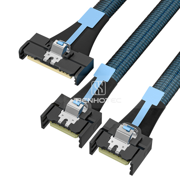
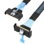
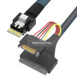
RHT-726-0003 is listed in Renhotec’s cable assembly range as an MCIO x8 to two MCIO x4 breakout cable. Branching is part of its configuration; it does not force a different product name.
The physical split alone does not establish system compatibility. Host support and the required electrical mapping still govern whether a breakout works in a particular system.
View the MCIO configurations · Read the MCIO connection guide
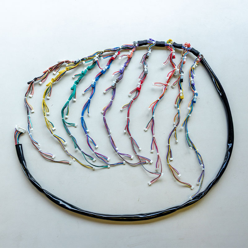
View the original Seiko Denki harness photograph.
Seiko Denki publishes this assembly in its own wire harness product gallery. The photograph shows a wrapped main run, groups of wires leaving at several locations, and connector housings at their ends. The layout makes the additional design task visible: both the endpoint connections and the positions of the outgoing groups need to be controlled.
The gallery does not identify a SKU, circuit map or ratings for this example. The photo illustrates construction only; it is not a Renhotec product.
TE’s HarnWare documentation includes tubing, molded parts and screen termination among harness construction operations. Protection is selected for the assembly’s service conditions; “harness” does not mean that the wires must remain exposed.
Compare the work the connection must perform. Some requirements affect one short lead; others affect an entire routed network. Neither name guarantees a lower price, higher durability or better electrical performance.
| Design question | A relatively simple connection | A distributed arrangement |
|---|---|---|
| Where does it connect? | Define each end, including any unterminated leads. | Define every endpoint and the wires or cables routed to it. |
| How does it fit? | Check length, exit direction, bend space and connector access. | Also locate branch departures, attachment points and installation clearances. |
| What protects it? | Specify the jacket, strain relief and any local sleeve or sealing arrangement. | Specify protection along the main run, branches and transitions where required. |
| How is it serviced? | Allow access to release and replace the connection. | Decide whether branches disconnect separately or the whole arrangement is replaced. |
| How is it accepted? | Check the required dimensions, termination quality and electrical connections. | Also verify branch identification, routing, attachment locations and the complete connection map. |
Both columns can describe products sold as cable assemblies or harnesses. They compare design tasks, not exclusive product categories.
Environmental protection needs its own specification. A sleeve used for abrasion protection does not by itself establish a waterproof assembly. Likewise, a shielded cable does not describe how the shield is connected at its ends. Define the complete arrangement and the conditions under which its performance is required.
Manufacturing acceptance also needs an agreed basis. IPC/WHMA-A-620 addresses requirements and acceptance for cable and wire harness assemblies. Where applicable, identify the required revision, class and any agreed exceptions. Naming a standard is not evidence that a particular supplier or product is certified.
A short, terminated cable and a many-branch harness are different jobs. A useful quotation comparison holds the connector selection, materials, lengths, protection, inspection requirements and order quantity consistent. Tooling, assembly labor and testing can change the result. The label alone is not a price rule.
Both cable assemblies and harnesses can involve cutting, stripping, termination, identification and inspection. The product name does not prescribe one manufacturing method. The difference is often how much work is needed to create a repeatable physical arrangement around those connections.
For a terminated jacketed cable, much of the assembly work is concentrated at its ends: prepare the jacket and conductors, fit the selected contacts and housings, and complete any specified shield connection, strain relief or molding. The sequence depends on the connector system; accessories that slide onto a cable may need fitting before the contacts or housing.
For a branched harness, the manufacturer must also organize the conductors along the main run, separate the required groups at each branch, and place identification and protective parts at the specified locations. A layout board or fixture can hold that geometry during assembly. It controls the physical arrangement; it does not replace the electrical connection information.
Seiko Denki describes cutting and stripping, crimping, and assembly against customer drawings or full-scale wiring boards. Its inspection checks dimensions, bundling positions, continuity and whether terminals are securely retained in their housings. This is a manufacturer’s documented process, not a requirement that every harness use the same equipment or operations.
Seiko Denki manufacturing process.
A continuity check can confirm an intended connection while missing a branch that leaves the main run in the wrong place. That branch may reach on a flat bench but become too short once the main run is clipped into the equipment. Similarly, a connector may fit the device but be too large to pass through the available opening.
Check the installation sequence as well as the finished position: which end passes through an opening first, where the assembly is secured, whether a latch can be reached, and whether a device can be removed without pulling on its wires. Service allowance should be deliberate. Too little can load a terminal; uncontrolled excess can interfere with nearby parts.
A first-article fit check is useful for a custom routed assembly because it examines this installed geometry. It complements dimensional and electrical inspection; it does not replace the specified acceptance tests.
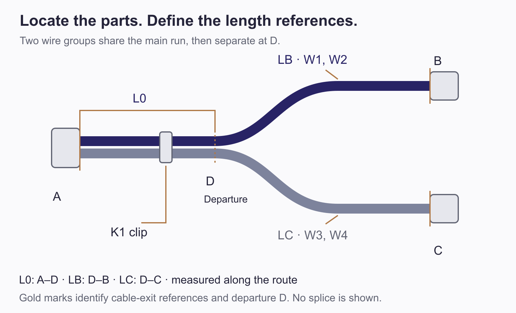
Suppose a controller must connect to two devices, with the wiring secured at K1. Label the assembly-side connectors A at the controller, B at one device and C at the other. “A harness from A to B and C” still leaves both electrical connections and installed fit unresolved. Work through the same assembly in three views.
The marked cable exits at A, B and C serve as the reference planes in this example. L0 runs from A to departure D; LB runs from D to B, and LC from D to C, following the route. On a production drawing, identify the exact connector reference planes and measurement method, including the assembly’s measurement condition. Dimension K1 from a stated datum, and specify tolerances and connector exit orientation.
The reference-to-reference route length from A to B is L0 + LB; from A to C it is L0 + LC. It is not necessarily the straight-line distance between the two connectors. Finished assembly dimensions also do not automatically equal wire cut lengths: termination preparation and the chosen measurement references must be accounted for.
Now identify each electrical path independently. The schedule below identifies the four wires represented by the two colored groups. For example, W3 runs from A/contact 3 along L0, leaves at D, then follows LC to C/contact 1. A real schedule must also specify the wire, terminal and any shielding requirements; contact numbering must match the stated mating-face or wire-entry view of the connector drawing.
| Wire ID | From | To |
|---|---|---|
| W1 | A / contact 1 | B / contact 1 |
| W2 | A / contact 2 | B / contact 2 |
| W3 | A / contact 3 | C / contact 1 |
| W4 | A / contact 4 | C / contact 2 |
If the design needs an electrical splice, give it its own identifier and define the connected wires and construction. A Y-shaped route alone is insufficient to specify that joint.
The bill of materials (BOM) identifies the connector housings, contacts, wire or cable, K1 clip, protection and labels by controlled part number or specification, with the required quantities. The drawing notes locate those parts and state assembly and inspection requirements. Specify whether mating halves belong to the delivered assembly or to the equipment.
For this example, moving device B may change LB and the relevant wire lengths without changing the from-to schedule. Changing a contact assignment changes the schedule and electrical check even if the physical route stays the same. A shared revision keeps those changes aligned.
Documentation basis: TE’s HarnWare design documentation describes assembly drawings, parts lists, wiring schematics and lay-up boards. The A–B–C example is an independent teaching example.
The drawing package defines the object; the remaining requirements establish how it must perform and how delivery will be accepted.
For Renhotec configurations, start with the relevant product SKU and describe the changes required. Discuss the proposed configuration through Renhotec’s custom connector and cable assembly service.