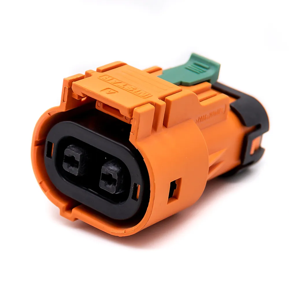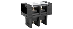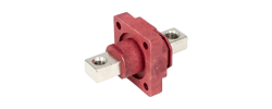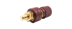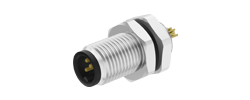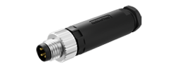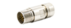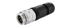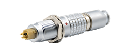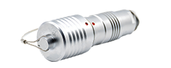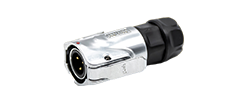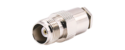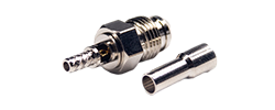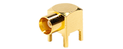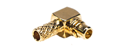
60A - 120A
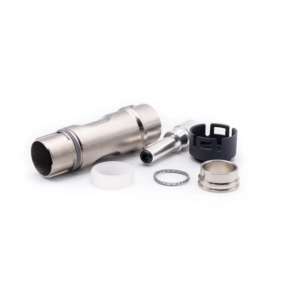
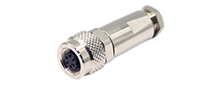
125A - 200A
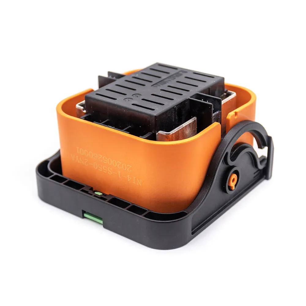
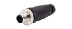
250A - 350A
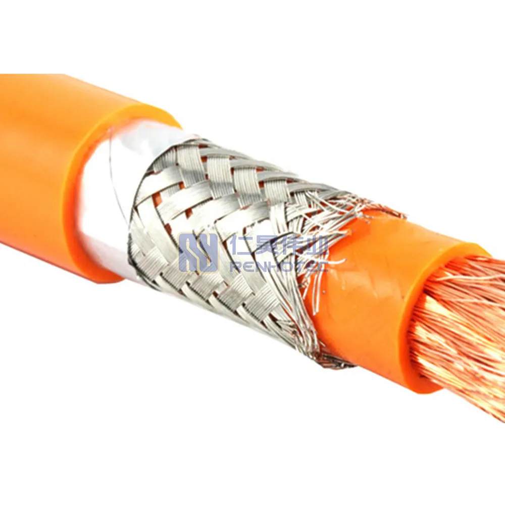
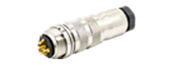
400A - 480A
On this page
Connector engineering
A connection must carry current where it belongs and keep separate circuits isolated. These tests examine different parts of that requirement.
Contact resistance measures the intended conducting connection. Insulation resistance measures isolation between points that should remain separate. A dielectric withstand, or hipot, test checks whether a specified insulation path withstands a stated electrical stress.
For a mated connector, the first question is how much resistance lies along a contact connection. The other questions concern paths across insulation: between separate circuits, or between contacts and another conductive part where the specification requires it. Housing-related tests use the surfaces and electrode arrangement specified by the method, including how to test an insulating housing.
Along a connection
Usually mΩ; an upper limit
Across insulation
Usually MΩ or GΩ; a lower limit
Across insulation under test stress
Voltage, time and failure criteria
Panasonic describes contact and insulation resistance in terms of these conducting and isolating paths. IEC also treats insulation resistance and voltage proof as separate connector test methods. Panasonic explanation · IEC 60512-3-1 · IEC 60512-4-1
Check the meaning of “hipot” in the report. It commonly means dielectric withstand voltage (DWV), but some cable-test documentation uses it as an umbrella for both DWV and insulation resistance. The report should identify whether the recorded result is IR or DWV. Cirris explains its use of the term.
A connector’s resistance specification may cover more than the microscopic mating interface. Depending on the sense-point locations, the reading can include terminal material, crimps or solder joints and lengths of conductor. Before comparing two numbers, establish the beginning and end of the measured segment.
Resistance produces voltage drop and heat in the conducting path. For a defined segment, V = IR and P = I²R. As a calculation example, 5 mΩ at 4 A gives a 20 mV drop and 0.08 W of dissipation. The 0.08 W is heat generated in that segment. Determining temperature rise and allowable current also requires the assembly’s heat-transfer conditions and ambient temperature.
A two-wire reading includes the test-lead resistance and the contact resistance where the probes touch the specimen. Those contributions can be significant when the target is only a few milliohms. Shorting the leads for a zero adjustment does not necessarily remove a changed probe-to-specimen contact.
Four-wire, or Kelvin, measurement separates the current-carrying leads from the voltage-sensing leads. The voltmeter measures the drop between the sense points while a known current flows through the test segment. This reduces the effect of the external test leads and their contacts. Any conductor or termination inside the sense span remains part of the measured segment. HIOKI’s two- and four-terminal measurement guide explains the distinction.
Kelvin connections address measurement error from the leads. Low-level contact resistance (LLCR), often described as a dry-circuit test, limits electrical excitation so that the measurement does not substantially alter surface films at the contact. A higher test voltage or current can change the condition being investigated. Select the connection method and the permitted test excitation separately.
Compare the meter’s selected range and mode with the product’s permitted test voltage and current. HIOKI’s RM3545, for example, offers a low-power mode with a 20 mV open-terminal ceiling and a maximum 1 mA measurement current. These settings describe the electrical excitation; the connector specification supplies the resistance acceptance limit. RM3545 low-power measurement description
A continuity indication shows that a path meets the tester’s configured threshold. To assess a milliohm requirement, compare a resistance result obtained over the specified measurement span with the applicable limit.
An insulation resistance test applies a specified DC voltage across an insulating path and determines resistance from the resulting current. Typical connector reports express the result in megohms or gigohms. Here, a larger resistance means less conductive leakage at the stated conditions; it is the opposite direction from the usual contact-resistance limit.
The unit distinction is substantial: 1 MΩ equals 1,000,000 Ω, while 1 mΩ equals 0.001 Ω. A table that loses the capital “M” changes the value by a factor of one billion. Keep the unit and the inequality together when copying a requirement.
The measured current can change after the DC voltage is applied as capacitance charges and the insulation responds. The specified reading time therefore matters. Surface condition, moisture, temperature and the fixture can also affect the result. Record the applied voltage, duration, test paths and environmental or conditioning requirements rather than reporting a resistance value alone. Ikonix’s insulation-resistance discussion explains the DC leakage measurement.
For an illustrative steady DC reading:
500 V ÷ 1,000 MΩ = 0.5 µA
The calculation relates a resistance reading to its steady DC leakage at 500 V. A DWV test uses its own specified voltage and current criterion; AC and charging currents are discussed below.
Write down which points were tested. “Between adjacent contacts” and “each isolated net against all other nets and a shield” describe different coverage. The network example below shows how intended connections affect this choice.
A reported result such as “>10 GΩ” gives a lower bound. Check whether it represents the instrument’s range limit or a configured reporting threshold. Also verify that the fixture reaches the intended test points: an unintended open connection can produce a high reading while leaving the specimen untested.
A dielectric withstand test applies a specified voltage across insulation for a stated period and checks the required failure criteria. These can include breakdown, flashover and a leakage-current limit. The procedure also determines how the voltage is applied and removed. A usable pass record identifies the voltage, waveform, test paths, duration and acceptance criteria.
Withstand testing can use AC or DC. Use the waveform required by the applicable test specification. AC current can include a capacitive component; a DC test has charging effects as voltage is applied. Those current components explain why a hipot current reading can differ from the steady DC leakage used to calculate IR. GW Instek’s AC/DC testing discussion describes these different responses.
Working voltage describes an operating rating within its specified conditions. Withstand voltage describes a test exposure. A breakdown test deliberately investigates failure as stress increases; a withstand requirement asks whether the specimen survives the prescribed exposure. Samtec-hosted guidance on voltage and power ratings discusses the rating distinction.
The S008.T02 family drawing, revision A/0 dated July 15, 2023, lists a rated voltage of 1500 V DC, a withstand test of 3000 V AC for 1 minute, and insulation resistance of at least 1000 MΩ. Here, 1500 V DC is the operating rating; 3000 V AC describes a one-minute test exposure. To define an IR test from the 1000 MΩ limit, obtain the measurement voltage, reading time and test paths—the drawing does not give those conditions.
Read the S008.T02 A/0 drawing. The S008 panel-connection article covers the mechanical application separately.
Select the test voltage and waveform from the governing product specification and method. An AC-to-DC substitution needs an explicitly permitted procedure; a higher voltage changes the applied stress and can damage the specimen.
High-voltage tests require trained personnel, a suitable guarded or interlocked setup, and the specified isolation and discharge procedures.
TE’s Power Double Lock specification 108-5410, Rev K3 (January 10, 2024), documents all three requirements together. The values below apply to the Power Double Lock system covered by that revision.
| Test | Requirement | Conditions to retain |
|---|---|---|
| Low-level termination resistance | Initial ≤10 mΩ Final ≤20 mΩ | Mated connector; <100 mA, <20 mV; subtract wire bulk resistance. Measurement arrangement: Figures 2 and 3. |
| Insulation resistance | Initial ≥1000 MΩ Final ≥500 MΩ | 500 V DC for 2 minutes; specified adjacent-circuit and housing/contact tests on a mated connector. |
| Dielectric withstand | No creep discharge or flashover; leakage ≤5 mA | Mated connector; 2.2 kV AC for 1 minute at sea level. Between adjacent circuits, and between housing and all contacts. |
Source: TE product specification, page 2. “Final” refers to the applicable qualification sequence; page 10 defines the test groups. The procedures cite EIA-364-23, EIA-364-21 and EIA-364-20 (Method A, Condition 1) respectively.
For the test arrangement, follow the methods cited in the table and source note. Page 11 adds the environmental conditions and specimen preparation requirements.
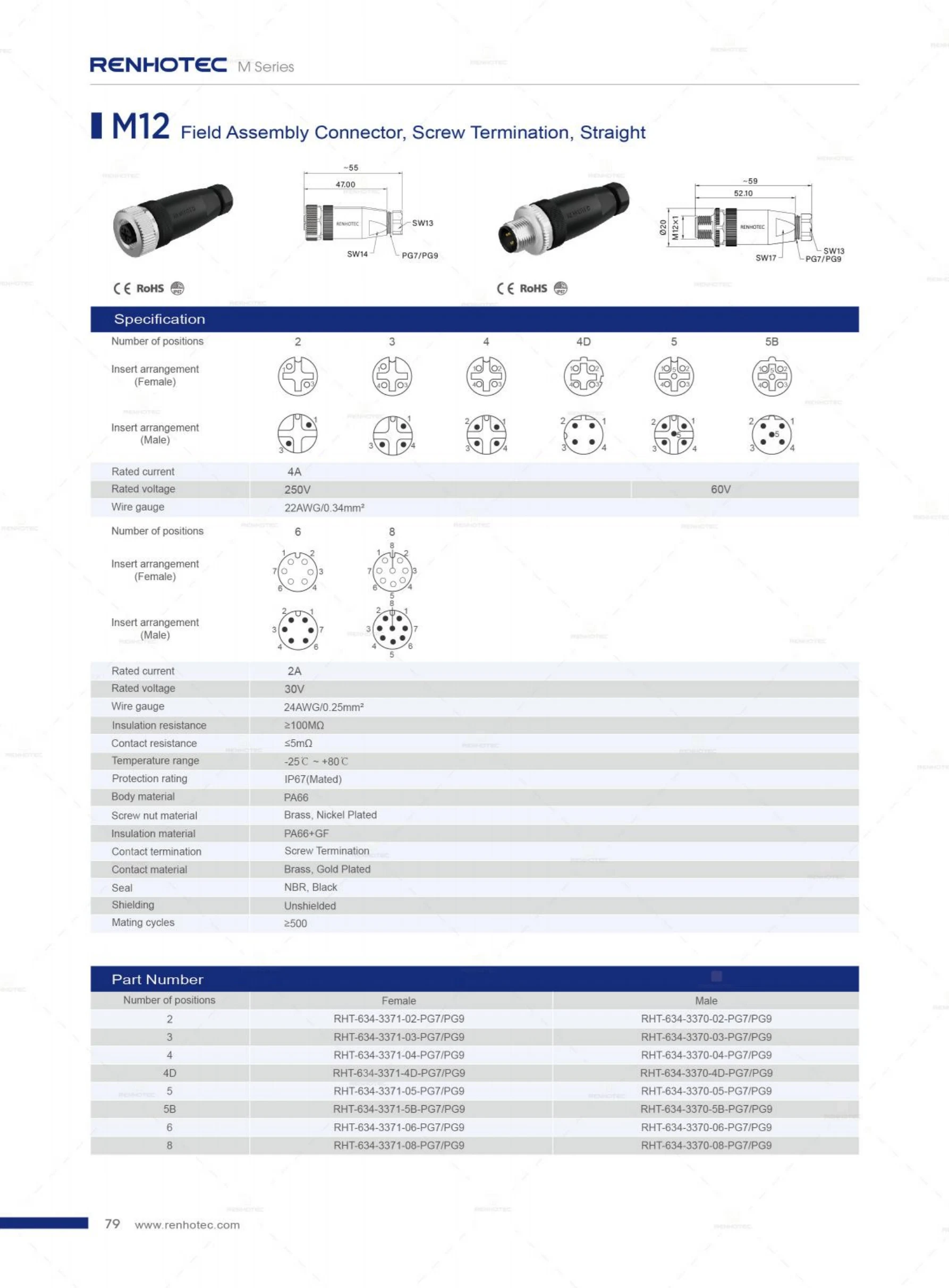
Page 79 of the M Series catalog lists contact resistance ≤5 mΩ and insulation resistance ≥100 MΩ for the straight screw-termination field-assembly connector group. Its ordering table includes the four-position male RHT-634-3370-04-PG7 configuration.
The catalog establishes the two limits. A test plan for this M12 configuration still needs the resistance measurement span and excitation, the IR voltage and reading time, and the applicable DWV procedure. Those conditions are absent from this catalog page.
RHT-634-3370-04-PG7 product details · M Series catalog excerpt, pages 79–80
Consider a report for a passive cable assembly that says “continuity passed” and “insulation resistance >100 MΩ.” It gives no test voltage, timing or network list. Review the report against the required connection and isolation tests:
A genuine contact-resistance failure and an insulation failure also lead to different investigations. The former concerns the intended conducting segment; the latter concerns an unwanted path between isolated points. Investigate the failed path by checking fixture contacts, the specimen, contamination and the test configuration.
For a cable or harness, start with the approved connection list. Points intentionally connected together form an electrical net. Isolation tests are applied between nets that are meant to remain separate, with shields, shells and unused points handled as the test plan requires. An intentional shield-to-shell bond belongs in the connection list; isolation coverage is defined around that intended connection.
Embedded resistors, capacitors, diodes or electronics can change the permissible high-voltage connections. Identify those components in the circuit and use a test program that accounts for the voltage across them. Cirris illustrates how its testers handle component-linked networks. High-voltage testing of cables with components
The connector terminology guide provides short definitions of continuity, open circuits and shorts. For acceptance, the applicable assembly drawing and test specification must turn those concepts into identifiable test points and criteria.
A useful request identifies both the product and the evidence required. Sending a connector part number with “100% electrically tested” leaves open which tests are performed, their coverage and the criteria used.
Give the connector or assembly part number, drawing revision, mating parts, conductor sizes and lengths where relevant. State whether testing is on a bare component, a terminated mated pair or the finished assembly. Identify initial testing and any required conditioning or qualification sequence.
For resistance, specify the measurement span, two- or four-wire method, permitted electrical excitation and any required conductor correction. For isolation, provide the network list and required net-to-net or net-to-shell coverage, including intentional bonds and embedded components.
Reference the governing method and product specification with revisions. Carry over the voltage or current, waveform, timing, applicable environment and limit for each test. State whether records must include individual readings, bounds, pass/fail results and sample identification, plus the agreed retest procedure.
Qualification evidence and routine production checks may use different programs. Ask which program produced the report and whether it answers your purchase requirement. Match each recorded result to the limit for its test stage: initial or after the specified conditioning.
“For RHT-634-3370-04-PG7, please identify the applicable mating configuration and test specification supporting the catalog’s ≤5 mΩ contact-resistance and ≥100 MΩ insulation-resistance limits. Include the measurement span, specimen state and test conditions. For the proposed finished cable assembly, confirm the separate resistance and isolation coverage, and the applicable dielectric-withstand requirement and report format.”
This request distinguishes published component limits from the additional information needed to accept a finished assembly. For a Renhotec review, send the part number, assembly drawing and applicable test requirements together.